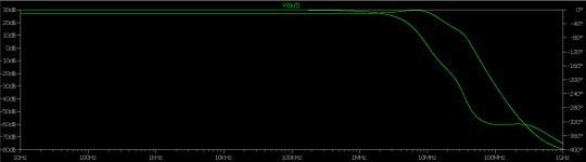
It was stable, but the phase margin was a bit short, in the region of 44°.
I have made some changes, and now it is well over 100°:
Thank you Elvee. Square wave has excessive overshoot issue with this one but I'm not sure that is it a bad indicator or not. I just added some pF parallel to fb resistor but it didn't help.
EDIT: Very low main compensation cap (C4) like ~10pF fixes it, but phase margin is in question again. Reducing R24 also helps.
Last edited:
Hi
having not much time to read thru the thread, I think anyway this amp cannot be redesigned for complimentary output stage and should not use high ft power BJTs without more redesign. Is that correct?
Have a look at this thread:
http://www.diyaudio.com/forums/solid-state/209907-building-elvees-circlophone-documentation-parts-accessories-beginner-friendly.html
CorrectHi
having not much time to read thru the thread, I think anyway this amp cannot be redesigned for complimentary output stage
Not quite: I have tested transistors having >30MHz Ft, and other members have gone further.and should not use high ft power BJTs without more redesign. Is that correct?
With attention to the layout and adaptation of the local compensations, it poses no particular problem
Thanks. I refer to the fT vs ic The original process 2N3055 was single diffused for these devices the fT vs ic is almost flat. But not so for triple diffused, multi-emitter etc. At ic about 50 mA fT is as low as 200 kHz, for ic = 2-4 A ft is 60 Mhz, for ic = 7 A and up fT is back to 100 kHz.
As i have some matched Sanken complimentary pairs...not nice that the circuit cannot be redesigned for complimentary OS
As i have some matched Sanken complimentary pairs...not nice that the circuit cannot be redesigned for complimentary OS
Well, the basic idea was precisely to avoid complementary pairs, because of the unavoidably imperfect matching inherent to the differences in N and P devices made from silicon..not nice that the circuit cannot be redesigned for complimentary OS
Same sex transistors can be perfectly symetrical.
Note that the principles, if not the architecture can be ported to complementary topologies. Serach for "symclophone" and "synclophone". These haven't been prototyped, but there is no reason they wouldn't work in practice.
Yes the thing with electrons and holes...the ratio of carrier mobility is 2, and that factor shows up everywhere, for ex. in the values of Cgs of MOSfets. Perfect complimentary pairs are not possible, but almost, and here BJTs excel over Mosfets. There is however no free lunch some price is to be paid in terms of level shifting, here with zeners, which are here avalanche diodes adding random noise ( at best ) and temperature coefficients. Anyway it is as symmetric as symmetric can go. Very clever topology the circlophone.
Actually, the zener doesn't serve for level-shifting (not in the common meaning anyway): its role is just to equalize, mostly thermally and a little Vce-wise the transistors of the VAS. Accuracy and noise have no detectable impact in this case.Yes the thing with electrons and holes...the ratio of carrier mobility is 2, and that factor shows up everywhere, for ex. in the values of Cgs of MOSfets. Perfect complimentary pairs are not possible, but almost, and here BJTs excel over Mosfets. There is however no free lunch some price is to be paid in terms of level shifting, here with zeners, which are here avalanche diodes adding random noise ( at best ) and temperature coefficients.
Work-arounds have been proposed, like an additional common-base transistor playing that role, but the effect is mostly aesthetic: it has no measurable or audible impact.
jikes..i didn't mention..i have a large heatsink with a pair of BD 250 C ( epibase pnp ft 3 Mhz) and a pair of 2SA 1295 ( ft 60 Mhz pnp) mounted, thus i need to invert all BJTs of the circuit to the respective opposite polarity. I think that should not cause a problem. Or?
No, it has been done, by Terranigma IIRC, the schematic must be somewhere in the thread...I think that should not cause a problem. Or?
But I'm sure you don't need to search, you can easily do it by yourself
Unfortunately it would be difficult to add a protection without losing many of the advantagesyes no problem. But one problem is protection shorted output at least.
It has been done too; I am not sure it has been described in the thread, but I have modded one of mine to serve as a replacement for an amp having a single supply.And hence...except for the bias of Q3 / Q4 it should not be a problem to make this circuit up for single rail PSU
That would be the simplest path to a protection( with current limit and cut off and/ or foldback characteristic)
if there are specials to take care of with the single rail please let me know. After all the PSU and the heatsink and 4 output BJTs exist, the rest can only take a few months ")
The PSU has 55 Volts DC max current 4 A , and adjustable overcurrent cut-off. The cutoff is quite fast about 2 milliseconds.
The PSU has 55 Volts DC max current 4 A , and adjustable overcurrent cut-off. The cutoff is quite fast about 2 milliseconds.
I'll try to remember: there must be issues like establishing the DC OP level without injecting ripple and things of the kind, but I need a bit of time to gather the bits and pieces, or even to reverse-engineer the one I have modded...if there are specials to take care of with the single rail please let me know.
- Home
- Amplifiers
- Solid State
- ♫♪ My little cheap Circlophone© ♫♪