The compensation amounts to a dominant pole scheme, but unlike the classical Miller of a "normal" amplifier, it doesn't have a negative impact on the slew rate, which is good.
It does have one serious drawback though: the corner frequency is pushed much lower in frequency, and as a result the loop gain*bandwidth product is only ~130KHz.
This means that the distortion is much higher.
Now we just have to find a scheme combining the best of both worlds...
It does have one serious drawback though: the corner frequency is pushed much lower in frequency, and as a result the loop gain*bandwidth product is only ~130KHz.
This means that the distortion is much higher.
Now we just have to find a scheme combining the best of both worlds...
I don't know why you say the GBWP is so low. In simulation it is 2.56MHz, and distortion at 1KHz is below .001% at 12V into 6R.
Remember I lowered R31 and R33, causing the input stage RC comp to become about 15 times bigger, but this is just an impedance thing, the loading hasn't changed. This scheme makes the amp as fast as it will go without significant overshoot.
Remember I lowered R31 and R33, causing the input stage RC comp to become about 15 times bigger, but this is just an impedance thing, the loading hasn't changed. This scheme makes the amp as fast as it will go without significant overshoot.
All my sims so far suggest CFP is only useful below 10KHz and it hurts BW and makes distortion a little worse at HF. So I'm going without it for the time being.
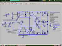
There are several ways to make this amp stable without significant overshoot, but this one has worked the best so far. My current simulation has a GBWP of 7.3MHz and a slew rate of 110V/uS. 1KHz distortion hasn't changed, but it is a whole lot faster. This causes stipulations.
At this point the input would become a GDO and would need to be shorted to ground with several hundred pF, and even that may not be enough. An input buffer would trivialize this, but that adds a transistor to the circuit and may complicate DC offset. The Jfet buffered schematic I've seen would probably work well for this. Ground plane may also help.
THD at 1KHz is still about .0034% at 12V into 6R. BUT, at 20KHz it has been brought down from .02% to .006%.
There is a problem with the speed. When slewing the VAS tends to go into class B, and this causes a jump in output current bias while switching, up to several amps. Thus I've fitted the Schottkeys across the VAS. This limits the slew rate to 60V/uS, except it's the diodes that are saturating, not the VAS or the output stage. Small signal behavior is the same.
Attachments
Last edited:
OK, I had missed the resistors change, now I am a little under 1MHz, but that's probably down to the different types of transistors you used.Remember I lowered R31 and R33, causing the input stage RC comp to become about 15 times bigger, but this is just an impedance thing, the loading hasn't changed.
A problem with low value resistors is the bias current, which is only moderately improved compared to a non-CFP stage.
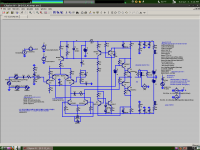
In my simulations distortion increases by 20 times if you have a 25k source impedance, which will occur if you use a 50k volume pot.
CFP helps with this, but I think an input buffer may be better for this specific problem. We could buffer the entire LTP with the same number of transistors. With this schematic distortion only increases by 2.5% when 25k input impedance is used.
CFP helps with this, but I think an input buffer may be better for this specific problem. We could buffer the entire LTP with the same number of transistors. With this schematic distortion only increases by 2.5% when 25k input impedance is used.
Attachments
if you have a 25k source impedance, which will occur if you use a 50k volume pot.
It should 25 kOhm maximum for a 100 kOhm pot with a preceding voltage source, 50 kOhm from cursor to ground in parallel with 50 kOhm from cursor to source.
With modern audio components, one should never use more than 10 kohm for volume control pots.
It should 25 kOhm maximum for a 100 kOhm pot with a preceding voltage source, 50 kOhm from cursor to ground in parallel with 50 kOhm from cursor to source.
With modern audio components, one should never use more than 10 kohm for volume control pots.
Last edited:
Good day!
I tried to follow you clever guys on this amp and now I know why there is a strong movement back to tubes. Like the old Mullard 5/10 or 5/20 circuits!!!!!!!!!!!!!! Can it still be called the circlophone? JUst wondering!!! I still have the book published by Mullard and remembered them 5/10's feeding the p.a. systems of Johannesburg station. I know I serviced them in 1968. When I was in the college we had them and you could hear 10 watts mono for about three kilometres on a farm . Oh for the quiet life!!! I saw an ad for the latest from Korea and only the digital part was transistorised.
I tried to follow you clever guys on this amp and now I know why there is a strong movement back to tubes. Like the old Mullard 5/10 or 5/20 circuits!!!!!!!!!!!!!! Can it still be called the circlophone? JUst wondering!!! I still have the book published by Mullard and remembered them 5/10's feeding the p.a. systems of Johannesburg station. I know I serviced them in 1968. When I was in the college we had them and you could hear 10 watts mono for about three kilometres on a farm . Oh for the quiet life!!! I saw an ad for the latest from Korea and only the digital part was transistorised.
I stand corrected.
I have a 100k stepped attenuator I'm using, my amp has an input impedance of 150k (buffered, so source impedance is hardly an issue). Before this, changing from a 10k pot to a 50k pot made a big improvement. I suspect it is soundcard issues since I'm using an on-board card (stac9227). Lately I've decrease the soundcard volume and increased my amp volume, this too seems to help.
I have a 100k stepped attenuator I'm using, my amp has an input impedance of 150k (buffered, so source impedance is hardly an issue). Before this, changing from a 10k pot to a 50k pot made a big improvement. I suspect it is soundcard issues since I'm using an on-board card (stac9227). Lately I've decrease the soundcard volume and increased my amp volume, this too seems to help.
The peculiarity of the input impedance has been signaled from the beginning:In my simulations distortion increases by 20 times if you have a 25k source impedance, which will occur if you use a 50k volume pot.
CFP helps with this, but I think an input buffer may be better for this specific problem. We could buffer the entire LTP with the same number of transistors. With this schematic distortion only increases by 2.5% when 25k input impedance is used.
Here are some additional characteristics and information:
.....
The input resistance is ~10K, but the source impedance is preferably kept below 1K, because of the base current modulation caused by the bias servo.
It is an annoyance, but a relatively minor one in a semiconductor environment, where impedances are best kept low: a 4.7K pot brings practically no degradation
On an other subject, I was aware that a "decompensated" version could be made stable in sim, but in practice I was never able to reach stability without the additional components.
However, my tests were made with closed loop gains ranging from 10 to ~20.
It might be stable at higher gains, I didn't test it.
The more you clamp down on a marginally stable open loop,
the worse Bode seems to peak right there at the end, where
phase gets all shifty and stuff...
In Class B, you got a reset that quenches some modes of
parasitic oscillation and ringing each crossing. But if there
is a huge peak in Bode, even such a reset might come too
little too late.
The differential mode open loop gain may be much lower in
crossing, because modulation from the common mode closed
loop works to smother it. Less open gain is more stable. But
in this case, is it real? Does it apply? Are we hiding a closed
loop peak that we would see if we look away from crossing?
Can we allow common closed within our Bode of differential
open. Or must we analyze all four cases of open open, open
closed, closed open, closed closed?
Because open differential closed common gain is higher off-
center, and higher for large signals that do not dwell in the
B crossing, is it still stable with a small DC offset to inhibit
the crossing reset? Or would that just be the same Bode as
both loops open?
Last edited:
. . .However, my tests were made with closed loop gains ranging from 10 to ~20. It might be stable at higher gains, I didn't test it.
With a modern source and with gain at potential, if 30+30vdc rails the feedback resistor should be 20k in real life. Therefore, what, proportionately should the feedback resistor be if 37+37vdc rails?Instead of increasing gain, the same thing could probly be done with degeneration.
Last edited:
The problem is not the input impedance but the bias current and degeneration will not help in this case.Instead of increasing gain, the same thing could probly be done with degeneration.
The bias current is dependent on the tail current, which is itself under the control of the servo.
I totally understand the input impedance and LTP base current issue. I was meaning for making the amp stable with smaller compensation values, without increasing gain so much. Degeneration is an alternative to this.
I found that using too much phase lead (say 47pF) compensation made the VAS compensation values skyrocket. It was better to use no phase lead or use the NFB network in my first schematic. I used a very small value in my later schematics (1.2pF) but this is not very practical.
I found that using too much phase lead (say 47pF) compensation made the VAS compensation values skyrocket. It was better to use no phase lead or use the NFB network in my first schematic. I used a very small value in my later schematics (1.2pF) but this is not very practical.
Yes, I tried that, But the problem is Bias starts at an indefinite level and drops instead of starting at 0 during startup. Furthermore, I suspect there is some kind of dynamic oscillation coming into play, causing the LTP to turn off and squelch noise when there is no input, based on what Dan has told me, unless he is exaggerating. Taking the LTP out of the servo loop would be great, but as I see there are good reasons for being the way it is in this circuit. Not that I totally understand the servo yet.
Kean taught me to do stuff with the simulator! Thanks man!!!
Well, I don't know what phase linear is for but this happened somehow when I was trying to follow all of the directions all at the same time. The THD figure has dropped down to 0.002620% even though the bias is also dropped to 100ma and this should be running desirably cool and efficient, so I guess we won't be needing those big fans after all.")
Well, I don't know what phase linear is for but this happened somehow when I was trying to follow all of the directions all at the same time. The THD figure has dropped down to 0.002620% even though the bias is also dropped to 100ma and this should be running desirably cool and efficient, so I guess we won't be needing those big fans after all.
Attachments
....Not that I totally understand the servo yet.
All this while, we've been trying to get Elvee to post a good explication for us dumbos! Let's hope he soon answers our prayers ...
All this while, we've been trying to get Elvee to post a good explication for us dumbos! Let's hope he soon answers our prayers ...
Let me reference Dan's above schematic.
I know something that may greatly clarify things for those who are confused. C2 seems to control the open-loop gain of the servo. This is because C1 acts as a high-pass across the BW of the loop. C2 acts as a low-pass, returning feedback phase to normal. This phase conversion causes R17 to act like phase lead compensation for the servo loop. I may be able to find a way to implement phase lag or other types of compensation to make the servo more stable and faster after I understand it well enough.
- Home
- Amplifiers
- Solid State
- ♫♪ My little cheap Circlophone© ♫♪