That's for people who don't do any phase inverting in the dark.Why this picture of an opto transistor of all the things ??
A 10MHz part for Vas might be unpleasant. I think that you might prefer a part at least 7 times faster than that.
you are correct, and in that case part needs to be ordered online, or be prepared to use other case styles....the crt boards on a pc monitor contains to77 npn's that are high fT's and high Vceo/hFE at the same time...
<http://sensing.honeywell.com/client_asset/document/3/9/2/2/2/document_AEB01BEC-BCA0-A8A7-43A04BFB7168B49A.jpg>
Why this picture of an opto transistor of all the things ??
Hi Prof,
Its a google thing, don't know why an image of an opto transistor has appeared...

Let me correct it, we might be getting the wrong impression here..
Regards!
Attachments
Allow me to present the following-- for what it is worth.
The last few days were spent in serious listening, some re-think -- and then some mods. We had always thought that it was better to use our gear to listen to music, and not use the music as the reason and the tool to listen to our equipment...
My apologies for sticking to the Chip amp; but it was familiar territory to our ears and I wanted to come to some definite (!) conclusions so that I could adopt a similar approach to the Circlophone project. With Elvee's eagle eyes over our shoulders, we were as impartial and objective as we could!
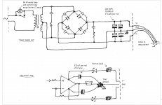
Please note the changes. The switch-on surge limiter has been moved to the transformer primary side. It is nothing more sophisticated than a 60W mains lamp and a switch. (which will soon be replaced by a power resistor and relay, with a 2-3 second delay.) The capbank now is 'pure' electrolytic, and nothing else. The (axial) caps are arrayed upside down, and connected by strips of solder-coated pcb material, one each for V+, V- and ground -- true power 'rails'.
Moving to the amp, there is a single 330 uF mounted on each supply pin. The 'isolation' Schottkys have been moved here, and the power input has a couple of small ferrite beads, which made a subtle but audible difference, all of us felt.
All I/we wish to say is, the whole exercise has been worth it!
With Elvee's approval this is what I would like to use with his 'baby'.
The last few days were spent in serious listening, some re-think -- and then some mods. We had always thought that it was better to use our gear to listen to music, and not use the music as the reason and the tool to listen to our equipment...
My apologies for sticking to the Chip amp; but it was familiar territory to our ears and I wanted to come to some definite (!) conclusions so that I could adopt a similar approach to the Circlophone project. With Elvee's eagle eyes over our shoulders, we were as impartial and objective as we could!
Please note the changes. The switch-on surge limiter has been moved to the transformer primary side. It is nothing more sophisticated than a 60W mains lamp and a switch. (which will soon be replaced by a power resistor and relay, with a 2-3 second delay.) The capbank now is 'pure' electrolytic, and nothing else. The (axial) caps are arrayed upside down, and connected by strips of solder-coated pcb material, one each for V+, V- and ground -- true power 'rails'.
Moving to the amp, there is a single 330 uF mounted on each supply pin. The 'isolation' Schottkys have been moved here, and the power input has a couple of small ferrite beads, which made a subtle but audible difference, all of us felt.
All I/we wish to say is, the whole exercise has been worth it!
With Elvee's approval this is what I would like to use with his 'baby'.
Attachments

Prof, normally you'd want to tune a power supply to a specific amp after you've built the amp. For example, it would be best to tune the power supply after you built a Circlophone.
Your original/earlier schematic was better, since it featured caps within the amplifier enclosure for speaker return bypass. The soundfield can be bigger when the return force from one channel doesn't invade the other channel, of a stereo amplifier.
Smoothing and storage are two different jobs--You wouldn't pump AC into a battery that's hooked directly to an audio amp. Likewise, we don't want to omit the smoothing section that should come before the cap bank. On your earlier schematic, you can use approximately 3,300uF caps directly upon the rectifier, next the inrush resistors, next the cap bank. . . aha! A nice clean CRC! When so much cleaner charge, your cap bank can be less excessive and therefore less expensive and still run much cleaner than before. It is important to do something technically good before tuning by ear.
See it modular in four sections:
Smoothing section (caps directly upon the bridge rectifier). Tank section (big cap bank). Speaker return bypass section (in the amp enclosure). Amp Bypass section (on the amp board). You can put Resistor or series diode or D//R, and interlink cable in-between any section in order to form CRC type structures.
Your original/earlier schematic was better, since it featured caps within the amplifier enclosure for speaker return bypass. The soundfield can be bigger when the return force from one channel doesn't invade the other channel, of a stereo amplifier.
Smoothing and storage are two different jobs--You wouldn't pump AC into a battery that's hooked directly to an audio amp. Likewise, we don't want to omit the smoothing section that should come before the cap bank. On your earlier schematic, you can use approximately 3,300uF caps directly upon the rectifier, next the inrush resistors, next the cap bank. . . aha! A nice clean CRC!
When so much cleaner charge, your cap bank can be less excessive and therefore less expensive and still run much cleaner than before. It is important to do something technically good before tuning by ear. See it modular in four sections:
Smoothing section (caps directly upon the bridge rectifier). Tank section (big cap bank). Speaker return bypass section (in the amp enclosure). Amp Bypass section (on the amp board). You can put Resistor or series diode or D//R, and interlink cable in-between any section in order to form CRC type structures.
@Dan: I would be happy with a "good" PSU that could do its job with any amp, of course, within limits. 'Tuning' is a good word, provided it is applied to fine-honing the basic traits of the PSU, rather than making it uniquely partner a particular amp. The requirements of the chip amp and Circlophone are not much different, and the power requirement could be as per spec. But here we are trying to decide on a 'topology' that is as near to the ideal as can be vis-a-vis its effect upon audible performance.
You seem to have ignored my mention of the serious listening exerise. The simple conventional, the complex earlier design, and then some were compared one-on-one. Then only we (three people, two much younger and with better hearing... ) arrived at the present simpler circuit. Please note that the smaller parallel caps were axed as they provided absolutely no audible improvements. (Believe me, it was not easy to decide to do that...) Do note that the small electrolytics on the IC pins were more than adequate, the isolation Schottkys (two each per channel) providing the 'dual mono' channel isolation of speaker returns. Moving the surge limiter to the primary side and switching it totally out of circuit after a few seconds improved things a lot, especially on sustained high-level, transient-rich signals. The capbank reservoir altered the character of the amp's delivery totally. If you are queasy about the speaker return, you may try a higher value cap on the IC pins/amp board.
Smoothing and storage might be two different things, but I dont think things work in that simple manner in the PSU circuit. And speaking of C-R-C filters, I would any day go for an L-C, all things considered. We have a lot of theory and "accepted" practices like bypassing a large cap with a smaller one and then a stilll smaller one etc. People have done a lot of analyses of CRC and LC filters and regulators, snubbers...what not. But doing the best job you know as per theory is one thing, and discovering that a simpler solution is better (audibly) is another. I would choose to go with something like this for my Circlotron (difficulties with some parts sourcing is holding it up)-- unless somebody convinced me I was committing "hara kiri" with such a design.
The above PSU mods were the result of careful 'elimination' -- and the "best man" won, I must say.
Now it is left to pundits like Elvee or others to guide us with some sensible theory -- and practice.
You seem to have ignored my mention of the serious listening exerise. The simple conventional, the complex earlier design, and then some were compared one-on-one. Then only we (three people, two much younger and with better hearing...
) arrived at the present simpler circuit. Please note that the smaller parallel caps were axed as they provided absolutely no audible improvements. (Believe me, it was not easy to decide to do that...) Do note that the small electrolytics on the IC pins were more than adequate, the isolation Schottkys (two each per channel) providing the 'dual mono' channel isolation of speaker returns. Moving the surge limiter to the primary side and switching it totally out of circuit after a few seconds improved things a lot, especially on sustained high-level, transient-rich signals. The capbank reservoir altered the character of the amp's delivery totally. If you are queasy about the speaker return, you may try a higher value cap on the IC pins/amp board.Smoothing and storage might be two different things, but I dont think things work in that simple manner in the PSU circuit. And speaking of C-R-C filters, I would any day go for an L-C, all things considered. We have a lot of theory and "accepted" practices like bypassing a large cap with a smaller one and then a stilll smaller one etc. People have done a lot of analyses of CRC and LC filters and regulators, snubbers...what not. But doing the best job you know as per theory is one thing, and discovering that a simpler solution is better (audibly) is another. I would choose to go with something like this for my Circlotron (difficulties with some parts sourcing is holding it up)-- unless somebody convinced me I was committing "hara kiri" with such a design.
The above PSU mods were the result of careful 'elimination' -- and the "best man" won, I must say.
Now it is left to pundits like Elvee or others to guide us with some sensible theory -- and practice.
Last edited:
A humble tribute to the Maestro -- for his knowledge, wisdom and that rare blend of saintly patience and indulgence!
Elvee, Sir, you ARE one of a kind!
Thank you!
I have not been very present these times, I have been busy investigating an issue raised by Piersma, and building a 12V adapter for the Circlophone.
Piersma and others have noticed that the CFP version has strong overshoot when subjected to a squarewave signal.
I have to remind everyone that, to date, the only "official" version of the Circlophone is still the original.
I have studied some variations, including the CFP, but I didn't optimize them the way the original was, or subject them to detailed and in-depth tests.
The behavior of the CFP is therefore not particularly surprising: I just made sure it was stable, and could reproduce music, but that's about it, and additional experimentation was advisable.
The first pic shows the problem simmed.
The second pic is the stability plot: it shows that the problem has nothing to do with the "linear" stability, which is excellent: in fact, the fast edges trigger instabilities between the two loops.
When a lowpass filter is placed at the input, the problem disappears (next pic).
That could be a possible fix, but it is possible to achieve better results with some fine-tuning of the compensations.
Only a moderate filtering is then necessary to remove any hint of "nervousness".
These modifications have practically no impact on the stability.
The final picture is the schematic of a simple charge-pump power adapter for those wanting to enjoy their Circlophone in their car.
I will post more details in the power supply section of the forum.
Attachments
Here is the link to the power adapter:
http://www.diyaudio.com/forums/power-supplies/212945-boostor-ideal-companion-circlophone-move.html
http://www.diyaudio.com/forums/power-supplies/212945-boostor-ideal-companion-circlophone-move.html
Yes, it is in the pipeline. I'll make tests and optimization on a physical circuit.Thank you Elvee for reissuing CFP version. Are you planning to share an official version of CFP further? Are you planning to analysis a real circuit?
In the mean time, existing CFP boards can already be upgraded, since the mods boil down to mere changes in component values.
I have investigated the effect of schottky diodes in the power rails.
Apart from the DC drop, the effect seems quite minor, see picture.
It somewhat raises the impedance of the supplies, leading to an increased modulation by the audio signal, but the effect is too small to have a negative impact on the performances of the Circlophone.
What could be the benefits?
As I said earlier, in multi-channel systems it could marginally increase the channel separation.
Other than that, it could also act as a signal-driven, dynamic low pass filter: at low currents, the diode's dynamic resistance is higher, lowering the cut off frequency.
It could contribute to reduce the no-signal hum for amplifiers having a poor PSRR, without wasting the power of an equivalent purely passive RC filter.
With the Circlophone, the effect will be much less apparent, because of the relatively high quiescent current
Attachments
Thank you Elvee, for allaying some of our anxieties.
But, what do you feel about the 'mods' that have been done in the interests of fidelity? That is, making the PSU a neutral and effective thing that would let the amp do its job, and facilitate that capably. My plan is to employ the same scheme --surge-limited 'heavy' capbank with snubbered diodes and R-C suppressors serve as the primary PSU, with a cable feeding the L-R channel Circlophones in a single enclosure, isolated by the two sets of Schottkys and bypassed by a single small (220 -- 470 uF) electrolytic at each supply node. Additionally I would want to cut the input ground trace and wire it directly to the 'star ground'. The input socket and the RF kill filter/low-pass will also have a direct lead to the star ground. The PCB main hi-current ground trace will have another connection to the star ground. This sort of wiring had given me the best possible results with medium power discrete amps in the past. This could be 'overkill' for the 'super-silent' Circlophone, though. Still your opinion counts... for many of us as the last word!
I gotta ask a foolish question. When a BAT54/85 cannot be had for D7, is it in any way possible to substitute it with a 1N5819, which is a 1 Amp rectifier?
And what about the 1N5822, a 3Amp rectifier, as stand-in for D4/5 ?
I've updated the builder's thread further to answer these questions and provide even more shopping links to click on. Conveniently, there's no need for wrong parts.When a BAT54/85 cannot be had for D7, is it in any way possible to substitute it with a 1N5819, which is a 1 Amp rectifier?
And what about the 1N5822, a 3Amp rectifier, as stand-in for D4/5 ?
"Rectifier schottky" at D7 will put disinformation into the sensor, eventually resulting in blown output devices. So, to avoid that problem, must use BAT type "signal schottky" There is a significant difference.
The spec for D4, D5 is "lowest forward voltage drop" and if you look at a 3A schottky's datasheet graphs they'll answer the question on how little current it takes to begin more extreme voltage drop that you don't want. Probably a 3A schottky will actually work for D4, D5 but "slack off" on the transients, cutting available power at possibly inappropriate moments, such as providing clipping instead of bass. Problem versus success depends on how much power output. For example: With the 25vdc+25vdc operating voltage shown in post 1 and with 8 ohm speakers (about 35 watts), then, in that case, using a 3A schottky for D4, D5 is okay.
Here is a link to datasheet for the 3A schottky shown in the post 1 (original) schematic). The forward voltage drop versus current graph provides the needed information.
Last edited:
Elvee told me that the reverse voltage spec isn't used since there's no reverse voltage employed at those locations. At D4/5, the 35v and 45v diodes are fine.Sir Daniel/Elvee,
I've been thinking of powering this amp at -/+50vdc, do I need to replace BAT85(D7) and MBR745 (D4/5) for a higher power rating?
Regards!
At D7, you could use BAT86 if you wanted a stronger part, but BAT85 will also do fine.
P.S.
There's no 50+50vdc listed on the constructors chart in the build thread. That voltage is possible but it could be abusive to the output devices. Perhaps you could employ a Fairchild Stealth diode bridge rectifier along with a CRC or CRCDC type power supply and drop a bit of voltage in trade for better filtering? The "slack" of a bit of current drop will help preserve the output devices. Hopefully you've got 8 ohm or 16 ohm speakers?
It so happen that what I had for a power transformer was -/+36vac...
I will be using 2SC5200s for the output and an 8 ohms speaker
I think you are going to surpass Daniel's goal.. except that you have 8 ohm speakers. 2sc5200 is a fast (30Mhz) device and it hink that it ain't to be a good start for a Circlophone. In Philippines, you could find a plenty variety of good transistors out there.
I think you are going to surpass Daniel's goal.. except that you have 8 ohm speakers. 2sc5200 is a fast (30Mhz) device and it hink that it ain't to be a good start for a Circlophone. In Philippines, you could find a plenty variety of good transistors out there.
It would surely take a trick power supply to save those output devices. They're rated for a 100w amp, not a 150w amp. Perhaps 4 of these trick diodes for a bridge rectifier (center tap config) and a CRCRC type power supply for yet more current dumping. Let's see, 7v drop plus about 2v more drop from the transformer. . . about 100w amplifier. That and some luck and some fuses would probably do. However, peak power might could be delivered to 150w (until the power caps run out), and if that took longer than the peak rating, then the output devices may not survive. So, we're definitely talking about a fuse party and maybe even a current dumper cable like a retail amplifier. That's how Kenwood does their Sanken's--the current dumper cable allows the high advertised figures while the long thin cable between rectifier and transformer migatates the difference between the transformer voltage and the output device SOAR.
-or-
Probably MJ15003 could do the job up at 150w. Those metal can devices have 250w dissipation rating. MJ21196 has a 3a to 1 second SOAR test and MJ15003 has a 5a to 1 second SOAR test. One plastic transistor, the MJW18020 has similar specs and should be able for the 150w. This power output also needs some relatively sturdy drivers.
Last edited:
- Home
- Amplifiers
- Solid State
- ♫♪ My little cheap Circlophone© ♫♪