Elvee, I have a simpler question: How do we adapt the inputs of Circlophone for supporting single rail operation?
Here is a way to do it.
I fact, I have already done it myself, because I wanted to upgrade an old amplifier with Circlophone boards.
Attachments
I wanted to try for auto-center at the output because a speaker doesn't need any sort of DC reference, and I have two single transformers not quite match for either voltage or current, yet wired as a single center tap and thus a trimmer doesn't have any right setting; and I have both a grounded amp and a grounded source with the grounds not quite match either.
So, does this (attached) scheme work with that scenario?
(the purpose of the attached schematic is to ask a question)
So, does this (attached) scheme work with that scenario?
(the purpose of the attached schematic is to ask a question)
Attachments
Here is a way to do it.
I fact, I have already done it myself, because I wanted to upgrade an old amplifier with Circlophone boards.
Exactly what quite a few of us would like to do! Thanks, Elvee!
")
I see a number of problems there:I wanted to try for auto-center at the output because a speaker doesn't need any sort of DC reference, and I have two single transformers not quite match for either voltage or current, yet wired as a single center tap and thus a trimmer doesn't have any right setting; and I have both a grounded amp and a grounded source with the grounds not quite match either.
So, does this (attached) scheme work with that scenario?
(the purpose of the attached schematic is to ask a question)
-Input and output are referenced to two different capacitive dividers; in an ideal world, it might work, but in practice, any mismatch between the capacitors will introduce ripple, and Elytics are not famed for accuracy.
-The input reference is created by 10K resistors dividers, and there is no blocking cap in series with R16, which means the DC gain will be high, and will amplify any offset disproportionately. Even with an AC coupled output this might cause troubles.
I think a better solution is to jettison completely the (pseudo) center tap, and act as if it was a true single supply. The scheme given in #901 then becomes applicable and suffers from none of these problems
Meanwhile, back to Split rail. . .
Thank you.
I was also wondering what sort of Split rail power supply you'd like to see used with Circlophone? For the builder's thread, it would be nice to have such an example.
I guess you would like a split rail CRC whereby R could be cable so as to get the "clean pair" very close to the amplifier boards. The boards have very little capacitance and so the speaker return forces needs someplace (else and nearby) to go.
I'd favor a polyester dip cap (or equivalent RC) as a load upon transformer secondaries, but I don't know what approximate values to suggest.
A crazy-simple start on a power circuit could be a pair of KBPC3502 (one per each secondary) with a large cap stuck right to each rectifier (conveniently cooled and mounted by bolting the rectifier to a surface). After that some resistance or cable to get the power near the amp boards and then. . . more cap(s) whereupon that is the location of power star and speaker return. That is applicable to both compact builds (might want a real "R"?) and separate enclosure for amp and power (interlink cable is "R"). I can't guess what values you'd like or even if this is a structure you'd like.
Perhaps you favor a fun schottky rectifier and if so, I'd like to hear about it--variable voltage drop isn't a bad thing since it can help sound be much more live if it doesn't also make noise. Noise? Well, I'm going to need some help for low noise.
Thanks again!
Keep it as simple as possible: transformer, rectifier bridge and 2 x 4700µ per ~60W channel is OK.Thank you.
I was also wondering what sort of Split rail power supply you'd like to see used with Circlophone? For the builder's thread, it would be nice to have such an example.
No need for something unusual or fancy
Anything that increases the supply impedance should be avoided, and this includes the R in the CRC.I guess you would like a split rail CRC whereby R could be cable so as to get the "clean pair" very close to the amplifier boards. The boards have very little capacitance and so the speaker return forces needs someplace (else and nearby) to go.
The on-board capacitors are sufficient for the HF return, and if there is a good wiring to the main filter caps, the supply will be nice and stiff at all frequencies.
With electrolytics, there is no need to damp parasitic inductance, which means there is no need to introduce additional resistance in the circuit
Such a capacitor is not needed, and if used indiscriminately could do more harm than good.I'd favor a polyester dip cap (or equivalent RC) as a load upon transformer secondaries, but I don't know what approximate values to suggest.
A snubber (10Ω + 220nF) could be useful if RF bypass capacitors are placed across the bridge's diodes.
Small ceramic capacitors (4.7nF) mounted directly on the diodes can be useful to suppress the HF noise caused by switching, and the PIN-diode-modulator effect in the presence of strong electromagnetic interference.
But without damping, they will cause ringing in the transformer, and this can be eliminated by using an appropriate snubber.
See aboveA crazy-simple start on a power circuit could be a pair of KBPC3502 (one per each secondary) with a large cap stuck right to each rectifier (conveniently cooled and mounted by bolting the rectifier to a surface). After that some resistance or cable to get the power near the amp boards and then. . . more cap(s) whereupon that is the location of power star and speaker return. That is applicable to both compact builds (might want a real "R"?) and separate enclosure for amp and power (interlink cable is "R"). I can't guess what values you'd like or even if this is a structure you'd like.
The only benefit of schottky's in a well designed supply is the lower voltage drop.Perhaps you favor a fun schottky rectifier and if so, I'd like to hear about it--variable voltage drop isn't a bad thing since it can help sound be much more live if it doesn't also make noise. Noise? Well, I'm going to need some help for low noise.
Any reverse-recovery effect of standard diodes can be addressed by suitable bypass capacitors.
In summary, the main design rule of a Circlophone supply is KISS and no-nonsense.
... In summary, the main design rule of a Circlophone supply is KISS and no-nonsense.
I couldn't agree more with Elvee's reminder about the KISS formula, and experience tells us it often is the best approach.
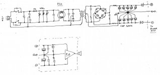
Still let me share with you the approach of one of my junior friends vis-a-vis a 'belt and braces' power supply for his 'Gainclone' (LM3886) amp, out of which he wanted to squeeze the best possible performance. Though many agree that the chip amp performs well with just a couple of thousand microfarads of filtering, this PSU with its large capacitor bank audibly improved the low end and the transient performance, while at the same time it "took away" something from the amp. But when the cap bank was isolated with a couple of diodes, the performance had both the goodness of the 'light filter' as well as the 'ease' provided by the heavy cap bank. I dont know what to make of it.
Perhaps Elvee would be kind enough to examine the question in detail and give us his recommendations.
Though that shouldn't bar us from experimenting with all sorts of combinations, looking for an audible improvement...
Attachments
Is there any possibility of a pcb group buy being set up by someone for this amp with a finalised BOM and build manual?
It seems to me that it would be a good addition to the amps offered as group buys normally.
Just a thought. I would be interested if there was a group buy.
It seems to me that it would be a good addition to the amps offered as group buys normally.
Just a thought. I would be interested if there was a group buy.
If I squint at that, it is a CRC with "D" instead of "R" and so there is some voltage drop but enforced to a regular amount.. . . But when the cap bank was isolated with a couple of diodes, the performance had both the goodness of the 'light filter' as well as the 'ease' provided by the heavy cap bank. I dont know what to make of it.
Circlophones can be built in many different sizes, all the way from 10 watts for your computer desktop amp to 130 watts for your big 3 way speakers, and beyond. This amp can use many different parts, but we have labored to make a shorter listing of selections for good results in the build manual (build thread). Here it is: http://www.diyaudio.com/forums/soli...tion-parts-accessories-beginner-friendly.htmlIs there any possibility of a pcb group buy being set up by someone for this amp with a finalized BOM and build manual?
It seems to me that it would be a good addition to the amps offered as group buys normally. Just a thought. I would be interested if there was a group buy.
A BOM (parts list)? Well, so far, everyone reads the schematic.
I've attempted to type out a BOM (attached). Please compare with the schematic to double-check.
Attachments
Last edited:
If I squint at that, it is a CRC with "D" instead of "R" and so there is some voltage drop but enforced to a regular amount.
Power supplies are quaint creatures, especially when they are complex.
I shall clarify my listening experience with the chip amp.
Mounting anything larger than a couple of thousand microfarads near the chip supply pins is well nigh impossible. And the chip amp sounds very good with just about 1,500 to 2,400 uF 'onboard'. However, the moment you wire up (connected by thick, but longer wires) something like 30,000 to 50,000 uF, "something is taken away" from the performance -- though the L F performance is very much enhanced, as also the way the amp handles transients. Well, of course, you could settle for a median value which could be a happy compromise. It was then that I suggested the pair of diodes. Quite a few of the listeners found that switching in the cap bank then provided an order of improvement without any compromise. Later, upon listening critically, I too came to share that feeling, though I have no explanations for what appears to have happened.
But I was wondering if we could try the same ploy here -- IF careful and knowledgeable designers like Elvee could explain any such possibility and guide us accordingly. Back in the college days in the 1970s, I could remember many of us skimping on beefy, expensive transformers, and opting to have instead a cap bank that audibly improved the performance of our homebrew amps. I am waiting for Elvee's advice.
Let's look at one difference.
The "gainclone" is carrying enough capacitance at the chip (at the amp board) to retard the speaker return force.
STK, TDA7293/4, Circlophone, and many discrete amplifiers are optimal with 220uF caps on the amplifier board, to support excellent clear small signal. This is not large enough to retard the speaker return force.
adapting. . .
Therefore, I suggest that whatever caps you liked on your gainclone be added offboard, at very close to the amplifier where you can also connect star ground and speaker return. At that point, you can connect your power supply diodes, cap bank, etc. . .
What do you think of that?
I also wonder what Elvee thinks of it?
Last edited:
It is a good, state of the art supply. I am not too sure about the effect of the diodes though. They could provide some isolation between multiple channels sharing the same supply, but other than that, I don't know.I couldn't agree more with Elvee's reminder about the KISS formula, and experience tells us it often is the best approach.
Still let me share with you the approach of one of my junior friends vis-a-vis a 'belt and braces' power supply for his 'Gainclone' (LM3886) amp, out of which he wanted to squeeze the best possible performance. Though many agree that the chip amp performs well with just a couple of thousand microfarads of filtering, this PSU with its large capacitor bank audibly improved the low end and the transient performance, while at the same time it "took away" something from the amp. But when the cap bank was isolated with a couple of diodes, the performance had both the goodness of the 'light filter' as well as the 'ease' provided by the heavy cap bank. I dont know what to make of it.
Perhaps Elvee would be kind enough to examine the question in detail and give us his recommendations.
Member Mickeymoose had proposed something, but it didn't have much success, probably for the reasons outlined by Daniel.Is there any possibility of a pcb group buy being set up by someone for this amp with a finalised BOM and build manual?
It seems to me that it would be a good addition to the amps offered as group buys normally.
Just a thought. I would be interested if there was a group buy.
Good capacitors are indeed more important for sonic performance.Back in the college days in the 1970s, I could remember many of us skimping on beefy, expensive transformers, and opting to have instead a cap bank that audibly improved the performance of our homebrew amps. I am waiting for Elvee's advice.
The only risk with undersized transformers is the amplifier running out of steam during sustained bursts of power, and also overheating of the transformer if it is abused for long periods. Transformers cope very well with short term overload.
Funny those 2N3055 remain the most popular transistor even though a stack others are available I remember when they just became available in the late sixties. Imagine a transistor that could handle 15 Amps! The wattage ability of 115watts was forgotton and I had fun with engineers that did not take that into consideration whilst I was only a technician meddling with them
If you want to build the best use only Texas or R.C.A. transistors. There is a reason why they sound better but I cannot put my hand onto the mag that contain the reason. It is in the manufacture the dies differ.
If you want to build the best use only Texas or R.C.A. transistors. There is a reason why they sound better but I cannot put my hand onto the mag that contain the reason. It is in the manufacture the dies differ.
Mickeymoose has several different versions. Deciding on which to use isn't easy. I believe that some people are afraid of the fan. But when I went to buy a board, the real problem was that there is no clear answer with so many options.Member Mickeymoose had proposed something, but it didn't have much success, probably for the reasons outlined by Daniel.
I actually like Terranigma and Piersma boards, since those are state of the art and fanless. They run the new CFP Circlophone edition. Terranigma's board is 5.7cm x 7.5cm (about 2.25 x 3 inches), has offset trim and has anti-heat-pooling design for cool running. It is a miniature marvel and the small size might be nicely cost effective for a group buy. Piersma's board is an update to Alex's and puts drivers and outputs onto one heatsink, which is the most convenient.
Perhaps Alex would like to update his board design to the CFP? Those who used Alex's board moved the fuses to the power board to get the fuses off the amp board and nobody put led's on the amp board. Most people did not use the output inductor. But the rest looked really very good.
Could you do me the favor of filling in the component values (and model numbers too, especially the diodes) on your power supply schematic. . . and also show the 1500uF or 2200uF from the gainclone's power circuit at the final output of the power supply schematic?But when the cap bank was isolated with a couple of diodes, the performance had both the goodness of the 'light filter' as well as the 'ease' provided by the heavy cap bank.
P.S.
I'm not suggesting to remove or replace the 100uF or 220uF from the Circlophone boards.
The Prof,

The drawing of your power supply is quite sophisticated, however the ground connection at the left of the cap bank is usually thought to be bad practice. Connection at the right, a few millimeters away from the "star", is much more recommended to keep the ground reference clean and may change the sonic character more than anything else.
The drawing of your power supply is quite sophisticated, however the ground connection at the left of the cap bank is usually thought to be bad practice. Connection at the right, a few millimeters away from the "star", is much more recommended to keep the ground reference clean and may change the sonic character more than anything else.
Daniel:
Mickeymoose has only one version of the C pcb. The first one built (tested by Elvee) was changed to correct some errors and incorporate Elvees suggestions
The fan is an option. A PIC micro controls its 3 speeds. The fan does not come on (slowest speed) until a LM35, mounted to the main heatsink, senses 120 deg.F. I myself do not like "turbulence generators" but I do like the safety back-up of the fan
My pcb design allows up to 9 Cs in a 3U-19" rack frame (power xformer not included) reminiscent of the old Altec Incremental amps. Each C has its own bridge rectifier etc
I am working on a 5+1 setup (2 Cs bridged for the sub) for myself that fits into a 3U frame, including an active xover and the xformer
Cheers, E
The "gainclone" is carrying enough capacitance at the chip (at the amp board) to retard the speaker return force....many discrete amplifiers are optimal with 220uF caps on the amplifier board, to support excellent clear small signal. This is not large enough to retard the speaker return force. ..
My apologies for the late response--two reasons for that; one, I am travelling, and two, as the PSU was the baby of one of our group, I had to check with him as regards some details.
@Dan:
I had a bit of difficulty understanding your terminology on ' retarding the speaker return force'. My mind goes back to those days when the +/- supply advocates were horrified by the output caps of single supply amps, which they wanted to abolish at all costs in the interests of fidelity. How easily they all forgot that the PSU caps were in-line of the a.f. currents. So, I guess you have here in mind the role of the filter caps to offer a ready path for the a.f. signal currents. As Elvee pointed out a few posts back, electrolytics are notorious for the accuracy of their values and so it is best to err on the high side when considering the l.f. limit.
I am sorry I just drew out a simplified version of the PSU that has apparently created a bit of confusion. The chip amp board (where you have a small pcb; many designs follow the point-to-point wiring method!) has 'normally' about 1,000 to 2,000 uF onboard, which is more than adequate. Many DIYers have reported that the amp 'sounds' best with that. Some finicky guys, like my young friend, have a 1,500 uF in parallel with a 100uF and another 0.1 uF. However, unless you have a beefy, regulated PSU, this meagre amount of capacitance is not adequate when the amp is driven by music, with the supply rails doing their own tap-dance. But we had observed that the addition of a really 'heavy' filter bank audibly detracted from the amp's 'sound'.
My humble suggestion then was to maintain the 1,500uF plus 'onboard' caps unchanged, and then beef up the PSU power reserves with a heavy cap bank. With the isolating diodes in circuit, the amp works normally with the a.f. signal currents routing themselves through the onboard caps. When the rails sag on account of drive, the virtually 'infinite reservoir' is connected, thus improving the transient and l.f. performance. This is the only practical explanation I could think of.
My friend has one heavy PSU with two sets of isolating diodes for the left and right channel amps; they are Schottkys salvaged from old SMPS.
The parts are largely non-critical, he tells me. The diodes are ordinary heavy-duty 10 Amp diodes bolted to aluminium angle off-cuts that are mounted on a strip of pcb material. He does not favour fast diodes, which he tried and says do not give any added advantages. The 'snubbers' are standard values, like about 5 kpF across the diodes and 0.22uF+6 to 10 Ohms. The noise filter is scrounged from an old SMPS. As for the MOVs, many knowledgeable designers advocate a parallel array of lower powered devices than one of higher rating. As for the transformer, many of us still go for an E-I core CRGO transformer -- if you have the space to mount it. The trick is to have the laminations put in a vat of wax BEFORE assembly, and then assemble meticulously--meaning, not like the "commercial method" of stacking half a dozen stampings together, but doing it individually. Use strong clamps for final assembly and then give it another boil in the wax vat, and pretty much nothing can touch that transformer. It is the quintessence of the "strong, silent type". And when you put in your cap bank, unlike a toroid, this doesnt pump in a lot of switch-on current, so that your current limiter need hardly be say, 0.5 or 0.33 Ohm after the transformer.
@forr:
Please do not take the rough drawing so literally. The mains 'earth' is fully isolated. The ground marking just indicates that the cap bank is 'earthed' to the PSU chassis in the interests of shielding. With isolating feet on the PSU, the amp doesnt care for that earthing. The amp is 'earthed' in the standard manner, with the 'star earth' connecting the filter caps and the speaker returns. The input signal earth needs to be a bit 'higher' than the star earth, and my friend has achieved that with a long piece of enamelled copper wire ( formed into a close wound inductance over another bit of thicker enamelled wire bit) connecting the input signal earth to the star earth. This also takes care of any 'rogue' RF signals too, he says from experience. You could also put in a resistor of a couple of Ohms or more here to lower the silence threshold of the amp. Earthing, as they say, is more an art! I hope this has cleared the air as regards the details.
Personally I am in favour of trying such a PSU with a diode-isolated cap bank with the Circlophone -- if only to verify whether it can provide the kind of improvement it has given with the chip amp.
Thank you for bearing with this rambling post.
- Home
- Amplifiers
- Solid State
- ♫♪ My little cheap Circlophone© ♫♪