To do that, it would be necessary to reduce their bias current, but it is not a good idea, it would blunt needlessly the performances for no obvious benefit.I am curious to know of what resistor and other values may change to optimize BC639 for Q5, Q6 (esp lower heat)
If we use a Pc max= 0.8W (depending on the manufacturer and conditions, it ranges from 0.6 to 1W), the theoretical maximum supply voltage is 60V.and what is the maximum permissible rail voltage without overheating the BC639?
to use for a small scale Circlophone.
It would be a darlington Circlophone also.. I found some genuine Philips BDV65B's. I think these gonna make sense for Dutch Circlophone
") . Mirroring current layout would be do most of job of darlington pcb imho.
. Mirroring current layout would be do most of job of darlington pcb imho.
Last edited:
Thanks to Elvee for saving me from counterfeit transistors!
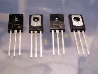
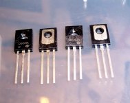
Here's a photographic comparison of fake versus real 2SB649.
As a reference for others, here are some pics of the fakes in question.
Unlike other fakes I have already seen, these are not "best efforts" to imitate the real thing: they have been carefully and cynically designed to dupe the unwary amateur at the absolute minimum cost: nice and clean case molding, and all easily accessible parameters like Vceo or capacitance OK.
But when you dig deeper, you notice that the Ft is only 34MHz (instead of 140MHz), and a scanning shows that the die size is that of the smallest small signal transistors, roughly 1/10th of what it should be.
If such transistors were used in the Circlophone, they would broadly seem to work at first.
They would give relatively poor performances, because of the pseudo-2SD669 low Ft, but the amplifier would sing, and the servo would catch up with most deficiencies.
But as soon as the volume is pushed up, things would go seriously wrong: with drivers so desperately undersized, their SOA would immediately be exceeded, with catastrophic results for the OP transistors, and maybe the speaker connected to the amplifier.
Beware, be always on your guard!
Attachments
If we use a Pc max= 0.8W (depending on the manufacturer and conditions, it ranges from 0.6 to 1W), the theoretical maximum supply voltage is 60V.what is the maximum permissible rail voltage without overheating the BC639?
That is well more than I hoped for.
If I understand correctly, a BC639 could work for at Q5, Q6 with the 25v rails of the Circlophone at Post 1?
The area of my chart that suggests Motorola/Onsemi MJE3055 (transistor and TO220 thermal pad, available in every shopping mall in the USA) is with "up to" ~22v rails, supports a wide variety of speaker loads and should be perfectly safe to use BC639 at Q5, Q6 with this smaller scale amplifier?
Reading this whole thread all again, suggests that R6, R7 can be 1K5 and I was asking what other non-disturbing way to lower dissipation at Q5, Q6 (or the entire board), even if the amount (per each step) happened to be very slight? The actual question is how to reduce the heat by any amount, at any location, without hindering performance.
My intended scale for "Miniature Circlophone" is with these transformers:
12+12vac (24vct), 13.5+13.5vac (27vct), 14+14vac (28vct), 15+15vac (30vct) for unregulated power.
For regulated power, one identical pair of 15vdc 90w laptop power packs that are double-insulated and have 2-conductor mains cords, are also usable, convenient, and low cost.
At this scale it seems that Philips ("PHI" gray case) Telefunken ("TFK") BD136, BD138 are usable for driver and their NOS market price of $5 is half as much as authentic Philips BD140, although new ST-BD140/HSB649/2SA1358/2SA968/2SA1930 all cost less than circa 1980's collectibles.
Before making up a schematic for "Miniature Circlophone" I'd like to know what value R21 and what single Zener for D8+D9 could work decently across a range of 15+15vdc rails to 20.5+20.5vdc rails? After the schematic, there is some possibility (probability) to generate a fairly orthodox miniature stereo Circlophone with NXP SMD parts for use with desktop/monitor speakers. It should be remarkable.
Last edited:
miniature stereo Circlophone with NXP SMD parts
This is exactly what was in my mind for a serious group buy project. That may be a very promising project to build a smd Circlophone with NXP transistors and MJL21194's at output.
Another thing is, Circlophone is very suitable concept for a very high quality mass production audio units.
Last edited:
Wow, the fakes pictured in posts 756 and 763 are decorated much differently except for the glossy case, all square edges, same size and exactly the same collector plate. Do your samples also do HFE ~245 if checked with digital multimeter test port?
Is there some conveniently rudimentary/simple circuit that can be used for a current handling test so as to explode the fakes before installing them in an amplifier? For example a simple sort of current test that anything suitably sturdy will survive if given a heatsink but the pervasive fake devices do not pass?
Is there some conveniently rudimentary/simple circuit that can be used for a current handling test so as to explode the fakes before installing them in an amplifier? For example a simple sort of current test that anything suitably sturdy will survive if given a heatsink but the pervasive fake devices do not pass?
If D10 (anti-latchup) cannot turn off due to nonstop workload of saving the amp from destruction, that may cause the amplifier to act as if C3 is shorted. In this condition, Circlophone will amplify DC if there is DC at input. In any case, there is the "dancing offset." If the amplifier isn't busy trying to latch up, D10 will shut off. The means to turn this off is to stop the root cause of the error condition. The actual error isn't located in the area of D10. But the odd condition means that a broken part needs to be replaced. If you fix the amp (bad transistor?), the safeties like D10 will sleep.
Last edited:
I am not very fond of BC639 as a VAS: depending on the manufacturer, there can be huge variations in the Ft and collector capacitance: it can reach up to 50pF, which is way too high.That is well more than I hoped for.
If I understand correctly, a BC639 could work for at Q5, Q6 with the 25v rails of the Circlophone at Post 1?
The area of my chart that suggests Motorola/Onsemi MJE3055 (transistor and TO220 thermal pad, available in every shopping mall in the USA) is with "up to" ~22v rails, supports a wide variety of speaker loads and should be perfectly safe to use BC639 at Q5, Q6 with this smaller scale amplifier?
You had found more modern and more suitable types if I remember correctly, BCP-something.
Modifying R6 7 will not change anything in the dissipation.Reading this whole thread all again, suggests that R6, R7 can be 1K5 and I was asking what other non-disturbing way to lower dissipation at Q5, Q6 (or the entire board), even if the amount (per each step) happened to be very slight? The actual question is how to reduce the heat by any amount, at any location, without hindering performance.
Anyway, trying fiddle a mW here and there is completely futile, since the basic philosophy underlying the Circlophone concept is to operate in warm class AB: that's what gives it its class A attributes, and every stage, VAS, drivers and OP dissipates significant amounts of quiescent power (and has to, to work properly and reliably).
Voltage of the zener ~= supply voltage, 500mW type suitable for up to 36V, 1.3W up to 100VBefore making up a schematic for "Miniature Circlophone" I'd like to know what value R21 and what single Zener for D8+D9 could work decently across a range of 15+15vdc rails to 20.5+20.5vdc rails?
If they are used in a 50mA CCS operated at 100V (with a proper heatsink), the real ones should survive indefinitely, but the fakes will be pushed far outside their SOA: this should be enough to separate the wheat from the chaff.Is there some conveniently rudimentary/simple circuit that can be used for a current handling test so as to explode the fakes before installing them in an amplifier? For example a simple sort of current test that anything suitably sturdy will survive if given a heatsink but the pervasive fake devices do not pass?
188 for the 2SD669Do your samples also do HFE ~245 if checked with digital multimeter test port?
182 for the 2SB649
Terranigma
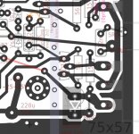
If you havent made your PCB yet, there is a small change that might improve it. I notice that the feedback is not taken directly from the output and the output is not in the middle of the track between the two ouput transistors.
As was described in an earler post this makes a significant difference to the distortion and whilst it is by no means bad as it is, you might see an improvment if you get it exactly matched.
I have seen 6dB improvemnts in very low distortion amplifiers just by getting this symetrical and the feedback taken directly from the output.
Regards,
Andrew
Elvee, what's your take on a low parts count DC Tracker, DC Servo? I'd sure like to try an active circuit instead of C3.
I do not see how such a circuit could be grafted to the Circlophone.
Anyway, a DC servo only makes sense when the DC performance/stability is very poor, as with some symetrical topologies, or at least to give an improvement over the existing situation.
In the Circlophone, the output DC offset is essentially that of the input LTP, unamplified, and to improve on that would require a monolithic pair, either just the pair itself like a 2SA798, or as part of an opamp that would perform a "classic" DC servo function to replace C3.
But frankly, I see no need for such a circuit, and if C3 annoys you, you can eliminate it completely and have a DC-coupled Circlophone, provided you choose (or hand pick) a low offset input pair.
Another possibility is to add an offset trimmer, but it would be a pity to depart from the completely adjustment-free philosophy of the Circlophone.
The need is. . . to try it for the purpose of quality leveling.. . .In the Circlophone, the output DC offset is essentially that of the input LTP, unamplified, and to improve on that would require a monolithic pair. . . But frankly, I see no need for such a circuit, and if C3 annoys you, you can eliminate it completely and have a DC-coupled Circlophone, provided you choose (or hand pick) a low offset input pair.
The case is when neither DC coupled nor the vast component manufacturing variety of the cap at C3. I'm near certain that we can do better than 2 diodes parallel with a random power cap, but there is only one way to know for sure.
DC servo:
Enhanced clarity just like a DC coupled amp, but without the caveats to dynamics and speaker safety.
DC servo:
Faster to build for the audiophile since there's no need to hunt for an optimized capacitor choice for C3 (quality control) if it is supplanted by an active circuit that promotes expected optimized results every time.
DC servo:
Not exactly have your cake and eat it too, but servo is excellent quality control.
Although it isn't particularly elegant and despite various reported possibilities from trimmers, it would be nifty to try it and find out its worth via actual performance. Due to wide variety of capacitor quality, for high fi use, the C3 area wasn't particularly adjustment free anyway and turning a dial is more efficient than swapping caps for quality control.Another possibility is to add an offset trimmer, but it would be a pity to depart from the completely adjustment-free philosophy of the Circlophone.
P.S.
For the record, I'd rather have an elegant servo to compare to trimmer to compare to C3. I seek your excellent guidance on how to best implement the servo and trimmer options, so they can be tried correctly.
That's the opposite: C3 works at the mA/mV level, and under such conditions even the crappiest chinese cap you could find on ebay would emulate a piece of wire, with degradation absolutely undetectable, even with the best instruments available.The case is when neither DC coupled nor the vast component manufacturing variety of the cap at C3. I'm near certain that we can do better than 2 diodes parallel with a random power cap, but there is only one way to know for sure.
By contrast, even a very good servo made with the best capacitors, opamps, etc, will introduce measurable impairments, noise, non-linearity, phase issues, etc.
Something else has to be considered: complexity. With a simple cap, nothing can go wrong, and to be absolutely sure the circuit can recover from any unforseen situation, diodes have been included to add a supplementary layer of safety.
They need not be implemented, this will change nothing.
But with opamps, an auxiliairy supply, etc, there is much more room for things to go wrong, and that could in the end easily cost a speaker.
Here is an offset adjustment circuit. It can be used with C3 present or shorted.
Attachments
Awesome!
And thank you for the explanation. Apparently, the effort of selecting optimized parts for a servo is not easier than effort of selecting a most pleasant model of capacitor and the audio quality results either way is the same at best, with other conditions probably favoring the cap as higher quality. Well, that certainly busts a few myths. Thanks!
And thank you for the explanation. Apparently, the effort of selecting optimized parts for a servo is not easier than effort of selecting a most pleasant model of capacitor and the audio quality results either way is the same at best, with other conditions probably favoring the cap as higher quality. Well, that certainly busts a few myths. Thanks!
If you combine the input capacitor (which can be a high quality one) with a shorted C3 and a low offset pair, or an offset adjustment, you get the best of both worlds: safety of an AC coupled amplifier, without servo or feedback cap issues.
That's the most reasonable and effective solution if you want to get rid of C3
That's the most reasonable and effective solution if you want to get rid of C3
Currently working on miniature size stereo Circlophone
Fairchild's KSA1220AYS for driver?
ST's BD911 for output?
These look somehow very interesting. That driver looks almost as good as a Philips? And that little TO220 output looks surprisingly durable for its size.
Fairchild's KSA1220AYS for driver?
ST's BD911 for output?
These look somehow very interesting. That driver looks almost as good as a Philips? And that little TO220 output looks surprisingly durable for its size.
Last edited:
Thank you!If you combine the input capacitor (which can be a high quality one) with a shorted C3 and a low offset pair, or an offset adjustment, you get the best of both worlds: safety of an AC coupled amplifier, without servo or feedback cap issues.
That's the most reasonable and effective solution if you want to get rid of C3
The point wasn't exactly to get rid of C3, but rather to make tests and comparisons both with and without C3.
With matched input, and temporarily shorted C3, it should be possible to choose reasonable but somewhat adjusted values for both R16 and R17 to result in zero offset. Your 10k input load spec makes this easier than usual. After zero offset, a wider variety of capacitors will make good results for C3 and then D11 won't misfire when the starting point is zero. For the record, I wouldn't promote a going without an NFB cap, on a high gain amplifier, except as a useful testing condition.
Some people say that all caps are good (myth), and some people say that all caps are bad (myth); But, the truth is that all caps are different. I believe that we should try about 5 varieties for finding favorable signal caps if they are in areas that also have gain applied. Optimizing signal cap selection is usually a task of choosing from amongst peers (not different than the task of choosing from amongst currently produced transistors via "test drive"), keeping the best results in circuit; however, in trade for slightly increased risk, the trimmer method is faster, easier and not component centric. The trimmer method could work for people who suffer capacitor myths or are in too much of a hurry to perform an optimized selection, and it could work fine for lower gain amplifiers.
Thanks again!
-----------
unrelated questions
For which rail of circlophone would it be most useful to add one 10uF cap?
I guess v-?
Which rail of circlophone would you choose to power just one LED+R?
I guess whichever rail drains slowest when the amp is powered off.
Last edited:
PCB status
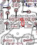
I tested a build depends on my actual layout so far.. and it suffered by that enormous offset problem again. I thought there is no reason to facing with same problem with a new layout except that if I didn't repeat same mistake again. Then I tracked pcb layout again and I detected a very annoying faulty track at input pair alignment. I thought that I didn't touch there but I remember I have cancelled alternative connection of 270p at post #708 but without removing that extra track completely. I fixed it but It didn't help for offset problem. I think I injured some place on circuit permanently.. And I'm about to rebuild it from scratch again despite that all of time consuming cost. Sorry for who waiting for good news again.
I tested a build depends on my actual layout so far.. and it suffered by that enormous offset problem again. I thought there is no reason to facing with same problem with a new layout except that if I didn't repeat same mistake again. Then I tracked pcb layout again and I detected a very annoying faulty track at input pair alignment. I thought that I didn't touch there but I remember I have cancelled alternative connection of 270p at post #708 but without removing that extra track completely. I fixed it but It didn't help for offset problem. I think I injured some place on circuit permanently.. And I'm about to rebuild it from scratch again despite that all of time consuming cost. Sorry for who waiting for good news again.
Attachments
Last edited:
- Home
- Amplifiers
- Solid State
- ♫♪ My little cheap Circlophone© ♫♪