OK, I gave it a try. First with BS107, out of laziness because they were the first small MOS I managed to find in my stock, but I knew they were far from ideal: being high voltage, they have a pretty large drain capacitance (30pF), and as a result the output showed a small oscillation on the negative excursion.it will be interesting to see anyone used mosfets in place of Q5/Q6 successfully.
Nothing spectacular or catastrophic, and rather harmless, it wouldn't have hurt the most delicate of tweeters, but nevertheless unacceptable.
It would also be manageable by altering the compensation, but there is no point in doing that, so after some more digging, I found a pair of BS170.
Not ideal either, but more suitable, and it worked perfectly and transparently, just like in the sim: just the two resistors increased to 2.7K.
 So, it's tried and tested, you are clear to try it for yourself.
 ")
2.7k instead of 1.2k. . . half the heat?
I'm trying to identify which mosfets that I have may be usable.
To do that I need specs, as suitable ranges low to high (that have center point as the average of the range) or center point figures. I made some headway, but it made a question.
MosFET
Polarity = N
Pd > 0.8W
Uds > 2*VS
Udg ??? V
Ugs ??? V
Id > 0.5A
Cd < ??? pF
Rds < ??? Ohm
The alltransistors.com equivalent parts search uses figures like these and then I'd check the results against vendor stock and then I go read all of the datasheets for all of the available parts. . . and I was fine up to that last step where I have no idea what I'm looking for other than a cute little MosFet.
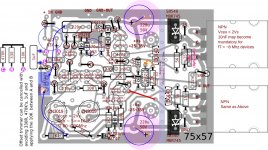
Well, that's true with one exception, and that is replacing Q5, Q6 is sometimes for the purpose of using higher voltage than 2N3019 could withstand. If a Circlophone has BC560C at input, then there's no need for Q5, Q6 to spec more than 120V, actually using not more than 100V because of output device SOA. Even so, that's a bit more than 60V. Most of your technician/constructor people have 64v or higher rails.
I'm trying to identify which mosfets that I have may be usable.
To do that I need specs, as suitable ranges low to high (that have center point as the average of the range) or center point figures. I made some headway, but it made a question.
MosFET
Polarity = N
Pd > 0.8W
Uds > 2*VS
Udg ??? V
Ugs ??? V
Id > 0.5A
Cd < ??? pF
Rds < ??? Ohm
The alltransistors.com equivalent parts search uses figures like these and then I'd check the results against vendor stock and then I go read all of the datasheets for all of the available parts. . . and I was fine up to that last step where I have no idea what I'm looking for other than a cute little MosFet.
Well, that's true with one exception, and that is replacing Q5, Q6 is sometimes for the purpose of using higher voltage than 2N3019 could withstand. If a Circlophone has BC560C at input, then there's no need for Q5, Q6 to spec more than 120V, actually using not more than 100V because of output device SOA. Even so, that's a bit more than 60V. Most of your technician/constructor people have 64v or higher rails.
Why do you think these resistors have an influence on the dissipation?2.7k instead of 1.2k. . . half the heat?
MosFET
Polarity = N
Pd > 0.8W
Uds > 2*VS
Udg ??? V
Ugs ??? V
Id > 0.5A
Cd < ??? pF
Rds < ??? Ohm
Overdesign is your enemy: if you specify Pd > 0.8W, and Id > 0.5A, you will end up with a selection of big transistors having huge capacitances and therefore unsuitable.
Here is a more reasonable approach:
Polarity = N
Pd < 1W
Uds > 2*VS
Udg irrelevant
Ugs irrelevant
Id < 0.5A
Cd < 15pF
Rds irrelevant
Alltransistors.com MosFet Search
Scrolling down to the bottom of that page. . .
I can't flip the < for the > as they are fixed. Therefore, the search tool is only partially effective. It does narrow down the amounts of datasheets to read.
Most useful specs would be described as a range of values, such as PD from what to what (0.5w to 1W?) and ID from what to what (0.4A to 1A?), and CD is probably 4 to 15.
At some point after knowing what I'm looking for, then I could start finding devices in stores.

Thank you sir!
These 120 volt devices will really help for higher voltage rails and/or for tolerating some power fluctuation. For authentic, look for the insulated Toshiba notch top case and elegant razor sharp print.
When availability is hindered, there's Toshiba 2SA1930, Fairchild KSA1220 drivers, but for vas there is Central Semiconductor 2N3500, 2N3501. And, Central Semi does have a SAMPLES program, so getting enough to build one stereo amplifier seems doable.
Limiter
For the circuit on the right side, so far, I found out, for zener, 6.2v is too much (activates at less than 10% RMS clean clip region), 3.6v is not enough (activates only during hard clip). The remaining options are 4.7, 5.1, 5.6.
Due to the wide operating voltage possibilities for circlophone, how do you calculate the resistor value from the rail voltage (assuming 5.1v 1/4w zeners run no harder than half current capacity at most, preferably less)?
CFP Circlophone PCB files
Hello all,
I finished my new CFP build without any problem so far. There is no reason to fail if any serious mistake hadn't made. I suggest to carefully clean remaining flux scrap, especially bottom of input pair alignment.
Attaching power schottkies on heatsink is not necessary. Power schottkies and driver transistors should be isolated anyway. If 10nf become necessary, it can be soldered directly B-E pins of upper power transistor also.
Hope you easy build for this Circlophone.
Attachments
Last edited:
The center design value for the current in the zeners is 5mA. That is not critical at all, and it could be halved or doubled without inconvenient.
For the circuit on the right side, so far, I found out, for zener, 6.2v is too much (activates at less than 10% RMS clean clip region), 3.6v is not enough (activates only during hard clip). The remaining options are 4.7, 5.1, 5.6.
Due to the wide operating voltage possibilities for circlophone, how do you calculate the resistor value from the rail voltage (assuming 5.1v 1/4w zeners run no harder than half current capacity at most, preferably less)?
With 5mA, a 6.2V zener would dissipate 6.2*5=30mW.
For 5mA, the resistor value is (Vsupply-Vzener)/(0.5*5) in kiloohm
Thanks for launching the builder's thread, that is something I should have done a long time ago.
Thanks for sharing, that is undoubtedly a very worthwhile improvement over the "plain vanilla" version, for a very modest increase in complexity.Hello all,
I finished my new CFP build without any problem so far. There is no reason to fail if any serious mistake hadn't made. I suggest to carefully clean remaining flux scrap, especially bottom of input pair alignment.
Attaching power schottkies on heatsink is not necessary. Power schottkies and driver transistors should be isolated anyway. If 10nf become necessary, it can be soldered directly B-E pins of upper power transistor also.
Hope you easy build for this Circlophone.
This is why I was such a pest about collecting information.Thanks for launching the builder's thread, that is something I should have done a long time ago.
I'm sorry that it is all in hypertext (many links) right now but it was a most expedient start. From that collection, I'm hoping to create a Word / Openoffice document later (can so easily be printed as a PDF). I also discovered that one cannot add or edit attachments beyond 30 minutes. The kludge solution is to make added posts for attachments and then employ the img tags to display the photos up in the first thread, since one can edit text.
I'd love to have your ideas on improving the documentation. The current phase is information collection. Did I miss anything?
The center design value for the current in the zeners is 5mA. That is not critical at all, and it could be halved or doubled without inconvenient. With 5mA, a 6.2V zener would dissipate 6.2*5=30mW. For 5mA, the resistor value is (Vsupply-Vzener)/(0.5*5) in kiloohm
I'm having a bit of trouble with it.
The the opto transistor triggered by output voltage doesn't do anything different than inversely series zener triggered by input voltage (posted earlier--my computer thump blocker located parallel to the 10k input load), since both simply hard clip the source instead of the amp, and I wonder if either could be used with a series resistor, as in turning on the ground leg of a voltage divider?
Unfortunately, none of the output based sensors work well. Like my ClipNipper, shown earlier, it is self defeating. The most they can do is break up long sections of clipping into short sections of clipping, which could help maintain safe operating area of woofer coil and Output devices, since both handle much more peak than constant. The function is useful, but the output isn't lovely.
Its appears somewhat illogical to sense the power amplifier output for this task--close barn door after horse got out. I think we need a tiny amp at input that doesn't carry audio signal, but really just for a sensor, to sense the input signal. It is unnecessary to sense clipping electronically; but, it would be more useful to have a human operated variable dial to set the switch on point. A "when" dial and a "how much" dial would be especially useful. The effectiveness (how much) doesn't have to be much greater than the soft clip function of a vacuum tube. But, I believe that we do have to locate an added voltage sensor at small signal input if we want to clip something other than the power amp or source.
No it works in the opposite direction: a clipper... clips when it is active, it clamps the signal to the zener's voltage, but the detector "steals" the zener's current when the output voltage is greater than Vsupply-Vzener.I'm having a bit of trouble with it.
The the opto transistor triggered by output voltage doesn't do anything different than inversely series zener triggered by input voltage (posted earlier--my computer thump blocker located parallel to the 10k input load), since both simply hard clip the source instead of the amp, and I wonder if either could be used with a series resistor, as in turning on the ground leg of a voltage divider?
Quite different
I don't like that kind of circuit anyway. But it is true that they can be made to operate smoothly and (almost) transparently. Peavey's system is a good example.Unfortunately, none of the output based sensors work well. Like my ClipNipper, shown earlier, it is self defeating. The most they can do is break up long sections of clipping into short sections of clipping, which could help maintain safe operating area of woofer coil and Output devices, since both handle much more peak than constant. The function is useful, but the output isn't lovely.
It has a logic to it: when you clip upstream, it works open-loop, it depends on the clipper having a clipping voltage just below that of the amplifier.Its appears somewhat illogical to sense the power amplifier output for this task--close barn door after horse got out.
But there are components tolerances issues, and even in an ideal world, the clipping threshold of the amplifier will vary with the mains voltage, the temperature, the state of charge of the filter caps, etc.
So, having a system using the actual rail voltages as a reference is a great improvement, it can never be wrong.
It also senses the the likelihood of clipping before it actually occurs.
That helps narrow down the zener choices. Right away, I'd remove 4.7v (too small) from the list. The 6v zeners "predicted" too early and almost nonstop (would remove a considerable amount of power), but maybe the point is to hold the amplifier's power down to a percentage of max.. . .It also senses the the likelihood of clipping before it actually occurs.
Apparently, I have a hot date with the desoldering iron for rework to figure out if 5.1v or 5.6v results in "a lot of LED blinking prior to a lot of noise" since the indicator must start flashing before clipping noise is heard.
This line of reasoning looks quite good for protecting the output devices of a high power amplifier; however, it doesn't look good for a "miniature circlophone" (BD911) where the 15~20v rails aren't enough. . . aren't enough for anything and wouldn't hurt the output devices either. In this case, it looks more reasonable to potentiometer > opamp (sensor) > diode > optocoupler/optoisolator, whereby the sensor's input is parallel with the power amp's input (both get the same input). Output of the op-amp is only going into the optocoupler/optoisolator. Since the optocoupler/optoisolator is only affecting the power amp (not the sensor), then the sensor can't turn itself off. So, I was thinking of clipping only the little op-amp, with the result never getting to the speakers. Gosh I wish I could write more sensibly.
Confoooozed!!! But I'll try it. . .The center design value for the current in the zeners is 5mA. That is not critical at all, and it could be halved or doubled without inconvenient. With 5mA, a 6.2V zener would dissipate 6.2*5=30mW. For 5mA, the resistor value is (Vsupply-Vzener)/(0.5*5) in kiloohm
(30-5.6)/2.5 = ~10k
That doesn't look right. SO much voltage, so tiny milliampers, I'd have automatically guessed 22k as enough to run, not wear.
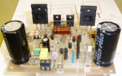
Pretty!!!hi all circlophone fans, The CFP Circlophone version.
I'm curious. What transistors and diodes are on it?
Last edited:
Here's a quick double check. . .hi Daniel,
The input complementary feedback pair = BC560C/BC550C
The phase splitter = 2SA1209
The outputpair combo = 2SA1837/MLJ21194
Powersupply voltage = 36V
best regards,
Piersma
CFP schematic doesn't show D8, D9. For 36vc unloaded? rails, I estimate (D8 of 16v) + (D9 of 18v) = 34v, assuming that 36v unloaded rails measure is probably more like 34v loaded.
For R21 (bias), I estimated 47k, although nearby values work.
Please double check VCEO voltage capacity at Q12, Q13, transistors (needs 80v or higher like KSC1845 or 2SC2240-BL) and current capacity at D4, D5 diodes (needs 5a or higher like MBR735, MBR745).
More device information is summarized at the builder's thread.
P.S.
Congrats on the really attractive looking project.
Transistors
hi Daniel,
For simulation purposes D8 and D9 are not neccessary, in real life you really need D8/9 otherwise Q5 would have to dissipate to much power. Q5 needs to stay within it's SOA. In my case i used 3 x 12V zeners, and for Q13 a 2SC2705.
For comprehensive eplanation Elvee will probably jump in.
best regards,
Piersma
Nice implementation, and good choice of transistors, I suppose you mean 2SC2911 for the phase splitter.hi Daniel,
The input complementary feedback pair = BC560C/BC550C
The phase splitter = 2SA1209
The outputpair combo = 2SA1837/MLJ21194
Powersupply voltage = 36V
best regards,
Piersma
However, the collector capacitance for this transistor is slightly below the recommended range of 5 to 15pF. This might cause minor stability issues (or not), depending on other semiconductors and other things.
The collector capacitance acts as an auxiliary self-compensation, which is why too low a value might be problematic.
If it happens, it will be in the multi-MHz range, very small and harmless both for the amplifier and the speaker, so nothing to worry about, and the cure is simple and straightforward: simply add 4.7pF C-B capacitors.
- Home
- Amplifiers
- Solid State
- ♫♪ My little cheap Circlophone© ♫♪