You see, I am researching in the same field...
http://www.diyaudio.com/forums/solid-state/188412-jas-just-another-sziklai.html
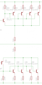
If you have alook on the JAS200 schematic , there is a twin OP configuratio, and I believe it can work until a quad.
For more I believe You would need a triple CFP like the Crown.
What still disturbs me is the driver degeneration resistor in this case (R13 and R14 in my schematics).
It should not be strictly necessary any more, once you have the OP Re ones, but there are other opporunities. I mention just two simple ones:
1) Join the two driver emitters with a single Re , NOT connected to the output line.
2) Replace the drivers RE with a Schottky diode.
I am very interested in a discussion on this topic, and it is one of the reason to was behind my simple design.
http://www.diyaudio.com/forums/solid-state/188412-jas-just-another-sziklai.html
If you have alook on the JAS200 schematic , there is a twin OP configuratio, and I believe it can work until a quad.
For more I believe You would need a triple CFP like the Crown.
What still disturbs me is the driver degeneration resistor in this case (R13 and R14 in my schematics).
It should not be strictly necessary any more, once you have the OP Re ones, but there are other opporunities. I mention just two simple ones:
1) Join the two driver emitters with a single Re , NOT connected to the output line.
2) Replace the drivers RE with a Schottky diode.
I am very interested in a discussion on this topic, and it is one of the reason to was behind my simple design.
I think you still need separate driver emitter resistors, because they have a role to play in the crossover region. For large signals (i.e. away from the crossover region), the output stage transconductance is set by this resistor. For small signals, you have two of these in parallel plus two CFPs in parallel - these must give roughly the same gm as 1/Re. This assumes low quiescent current. If you are happy with gm-doubling and rely on massive feedback to linearise the whole thing then you can ignore this.
The emitter resistors used to balance multiple output pairs (not needed for a single pair) will reduce gm, so a higher quiescent current will be needed.
The emitter resistors used to balance multiple output pairs (not needed for a single pair) will reduce gm, so a higher quiescent current will be needed.
Yes, that looks OK. The output emitter resistors encourage current sharing. The driver emitter/output collector resistor encourages clean handover in the crossover region.
Well, I thought it would be ok as well, it is what Rod Elliott recommends for his P3A, which is a CFP output stage, if you want to go higher than just 1 x pair. People have built it with 2 x pairs this way and adding 2 more pairs should not pose a problem.
But always good to get more opinions about it.
Of course, if you set it like the multiple pair P3A it works well like that. And the gm will be set by the Re because it will be dominat respect to the transistor internal one. But it needs more connections from the driver to the OPs, and it is more power lost on resistors. It does not help THD, either. Would´nt it work just like in the JAS 200? Note that there the Re is much bigger in value (i.e. 3.3 Ohm) that the one int the multiple pairs PA3, where ALL the load current passes through it.I think you still need separate driver emitter resistors, because they have a role to play in the crossover region. For large signals (i.e. away from the crossover region), the output stage transconductance is set by this resistor. For small signals, you have two of these in parallel plus two CFPs in parallel - these must give roughly the same gm as 1/Re. This assumes low quiescent current. If you are happy with gm-doubling and rely on massive feedback to linearise the whole thing then you can ignore this.
The emitter resistors used to balance multiple output pairs (not needed for a single pair) will reduce gm, so a higher quiescent current will be needed.
It is just for the driver (see JAS 200 schematic). As I said, I want to experiment alternative solutions, since the standard solution ( 6 power resistors for 4 power transistors, plus the additional wiring) looks also sub-optimal to me.
You don't actually need very high power resisitors for the mutiple output transistors. I paralelled 3 pairs, and used 2 x 0.22R 0.6W in parallel for each emitter resistor. Even SMD resistors can be used here, but then that makes it more difficult to repair should they blow (tracks could burn clean off).
Do higher resistance power resistors allow for more gain mismatch on the O.T's? Like if I have parallel 1 ohm emitter resistors (0.5 ohm) can I use MJ21195 and 2n6230s together? I hear pros like to use the same batch of the same part number for best gain match. Not expecting big SOA from the 2n6230's but I'm not going to run 2 ohm loads @ 22 amps per channel like the amp is spec'd at. 8 ohm loads. 95 V rails.
Last edited:
can I use MJ21195 and 2n6230s together?
Theoretically, yes. But not advisable. Transistors of same type (i.e., same part number) from same manufacturer already need current-sharing resistors. Altogether different types... who knows (different specs, different manufacturing process)? Going in the opposite direction: in ultra-low distortion amplifiers, transistor gains are very closely matched, done by individual measurement; even same-batch -edness might not be good enough to qualify them for selection.
This is another way, maybe a little more feasible. Replacing the Re with a diode may help smoothing the crossover. The effect of the diode would be negligible at higher swings, while stronger at the smaller.It is quite possible that you have seen it somewhere like that!
Attachments
This is another way, maybe a little more feasible. Replacing the Re with a diode may help smoothing the crossover. The effect of the diode would be negligible at higher swings, while stronger at the smaller.
Replacing Re with diode can results problem with the bias stability. Re helps quite lot, I would keep it, with very low value, say 0.05ohms or something similar.
Sajti
- Status
- This old topic is closed. If you want to reopen this topic, contact a moderator using the "Report Post" button.
- Home
- Amplifiers
- Solid State
- CFP multiple output pairs.