Hi there, I dunno if anyone is still watching this thread, but if you are I would appreciate some help.
I have a SA-12 that has one channel out, but has not blown any fuses, q1 as well as the outputs fet's are in good working order. I took some measurements and i am getting 7.5v on the gate for the n-type and .8v for the p-type, on the working channel these are roughly 3.5v on both types.
I have checked the 10v zeners and they are good, I am not sure where to go from here, any ideas?
Thanks in advance.
Hi konst,
I hate to say it, but it sounds like one or more of your outputs is damaged. Voltage on the gate as high as 7 volts is not good news. Long shot. Near the fuses on that channel, there are some zener diodes, capacitors and heat marks. There are resistors underneath the PCB and the entire mess gets cooked to death, including the PCB. However, the mosfets with a voltage of 7 volts would normally be turned hard on, so I'm still thinking you have bad outputs and possibly a destroyed bias circuit on the main PCB.
I have developed a modified output section that uses BJT outputs and sounds a lot better (backed up by measurements). I recently was infected with the Sporta trojan and lost everything on that hard drive. I designed PCBs for bias that mounted off-board to get by the damaged main board. The new circuit was much improved and reduced hum as well.
I made changes to the overall circuit that greatly improved distortion performance and reliability. I've had a prototype out in the field for over 10 years now without a failure. Too bad you're across the pond. So my hints for you are
1. You need three circuit boards (the other is an HV regulator).
2. The basic circuit needs to be changed to allow for much improved sound quality.
3. These are horribly unreliable in their stock form, and some "updated" units aren't any better.
I was authorized warranty for Counterpoint back then and learned a huge amount about them since. I've redesigned many preamplifiers as well.
One more chance for a happy outcome for you. Check the relays near the outputs for shorted contacts. That might cause the issue you are having. They are normal "form 2C" telecom relays. Buy gas sealed types for replacement. If you yank the relay and turn the amp on, that output will probably rail and bounce around, so don't put anything on that output until the other relay clicks. Then measure your gate lines. The more I think of your problem, the more I think you might be lucky and have a bad relay.
Those output mosfets have been NLA for a long time now. There are some new lateral mosfets made, but the pinout is completely different for the TO-3 cases. You can't use them without some heavy-duty rewiring of the output section. Note that the matching requirements are so tight for the output pairs that you will need to buy a bunch in order to get matches close enough to work. This is critical.
-Chris
SA-12
Hi There Anatech, actually since I last posted I have moved to SOCAL. 7years ago, and now I feel old (profile updated).
I pulled the relay after your reply last night but have not yet had time to test it.
I am very interested in your mods, not sure if you are happy discussing this in open forum, but I would be grateful for any advice, schematics etc. I am generally not afraid of a challenge.
I did take out all the transistors/fets and they all test good, and there is no major offset on the output or burnt resistors anywhere, so I am hoping that the relay is the main issue.
ON a different note, anyone else get nostalgic with the smell of burnt 80s PCBs? Bit like old cars, modern cars don't smell right when you take them apart.
Hi konst,
At the moment, my information is either in my head, in lab notes or encrypted and beyond my reach. These folks who write this type of code should all be found dead in an obviously messy and protracted, painful death.
For changes like this, I would have to have the amplifier up here. The SA-12 was not as nice as the SA-100 (I had more to work with in the SA-100). I might have to do something extra for SA-12 amplifiers. That and I'm changing the bias control in that prototype to improve it some more. The people who have the prototype don't want to bring it in again because they would really miss it.
I did the same general mod to an SA-100 and retained the Mosfets, didn't sound nearly as good as the "bipolar-100" mod. I have an original SA-100 for a control, and the "mosfet-100" as another reference. When I do upgrades, I need about three of the device to ensure the performance is always moving strongly up.
The person who is helping me wants a similar treatment for the SA-220. That won't happen until I'm happy with the SA-100.
-Chris
Hi there folks, I have done some work since my last post. I have resurrected a dead SA12 I bough on Efraud for 150bux. This has been interesting and quite rewarding, but before I start, PLEASE let me know if I am out of line posting this in this thread, and I'll start a separate one.
Let me also state that this is completely an amateur project with minimum previous experience, and I recommend you do not try this at home.
I purchased a really cheap dead SA12 on E*** a while back and was wondering what to do with it, until I came to the conclusion that refurbing it with modern components was probably the most excitement I was going to get for a while (having been married for almost two decades).
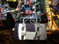
SO basically it occurred to me that as the original IRF130/9130 are no longer available, I should use a modern MOSFET and I went with NP's favorite IRFP240/9240.
I used NP's matching method and got the outputs to within 2mv and rewired for the non TO3 configuration. Below is a early picture of the new layout, it is messy, and gets cleaned up later on (disclaimer, I only do this for fun, I am strictly amateur and self taught, with help of some friends, do not try this at home).
(more tomorrow)
Attachments
Last edited:
@Konst Oops I just realized I went down the express-route ofyour scenic route documented in SA12 odyssey!
The only difference is I went straight for balancing source resistors of miniscule value to avoid having to match output devices. I did that because it seems all the similair reference designs out there point to anywhere between 0.1ohm and 0.33ohm source R per device at the output.
Powers up nicely right from the get-go and I started with a low low gate voltage after making mistakes with old original mosfets repairing previous units, and I am running 250mA, and the transformer doesnt sound/feel stressed at all.
I picked the 240/9240 simply because they are affordable unlike the Toshibas commanding crazy prices out there.
Cheers,
Last edited:
Hi phi70,
You got yours functioning, but it sounds like scrap compared to how they should sound. I know this because I have seen others come in repaired like that and the owners were complaining about. With the bipolar stage they sound far better than they did originally. To be honest, the output stage always was very poorly designed. Same for the power supply.
-Chris
If they did, I would be repairing them that way. They don't work well, and I get the feeling you didn't match them nearly as closely as they have to be to be reliable. The cost in labour for matching is gruesome alone. That's why I have designed a bipolar output stage for those. The other skilled Counterpoint tech I know of also did the same thing (a different way).Vishay IRFP240 and 9240 Hexfets. Dirt cheap and you can revive these dead units rather easily.
You got yours functioning, but it sounds like scrap compared to how they should sound. I know this because I have seen others come in repaired like that and the owners were complaining about. With the bipolar stage they sound far better than they did originally. To be honest, the output stage always was very poorly designed. Same for the power supply.
-Chris
Completely understand. But there's a cost+covenience target in this project.
For B+ I would add a section to the 2 gain stages to avoid anode coupling and use a
Maida regulator at least, get a beefier tube for follower and run a 6FQ7 at at least 5mA per triode for SA12 and perhaps 7mA SRPP for SA100.
I do have a stock SA100 for AB comparison and with due respect (you are most definitely the expert) this revived unit doesnt sound like crap to me on my Avalon Eidolon Diamond. With a bipolar stage I will need to build daughter boards and use driver transistors in addition to the output devices, making it almost like an NP100.
Hi phi70,
There are design errors with the gain and "driver" stages as well. A rebuild creates an amplifier that I think would have been the original intention. People with my rebuild are all stunned by the sound quality increase.
I redesigned the amplifier using the original output stage, and it sounded massively better (other people's opinion). The bipolar output stage on PCBs sounded markedly better. Only one SA-100 was left with the mosfet output stage. Everyone else went for the bipolar stage. The bipolars run at much lower bias current and the transformer is much cooler.
I never judge my own work - ever. It's too easy to fool yourself. I'm actually very pessimistic when it comes to judging what I do. Anyway, there are improvements I am making, and I had to buy my own chassis' to work with as the experimental amplifier never gets returned. I kept one original amplifier to compare against. A reference.
You don't need to go to extremes with the HV regulator at all. A simple regulator does wonders. But the basic design is messed up in a few basic ways. Once the basic design errors are fixed, the sound quality really comes out.
Is it worth it? Every single person I have done an amplifier for has only been sorry the amplifier was done years ago. I'm not suggesting you send it in to me. Study the design, fix it and put a bipolar stage in it. Do it right and you retain the Counterpoint sound as I have - just a lot cleaner, more reliable and more stable. I'm not about to release the details. It took a ton of time and prototypes to get it right. But it is possible to make this a Counterpoint that is a great deal more desirable. Once you hear one fixed you will not be able to listen to the one you have.
-Chris
- Home
- Amplifiers
- Solid State
- Counterpoint SA12: What's that smell?