What IS that smell? As they say, a picture is worth a thousand words...
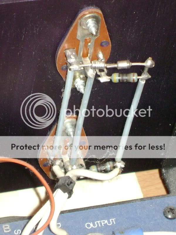
This is what I found last night after pulling my Counterpoint amp out of the cabinet and opening it up for a look...toasty resistors on the output stage of the left channel. I also found this...
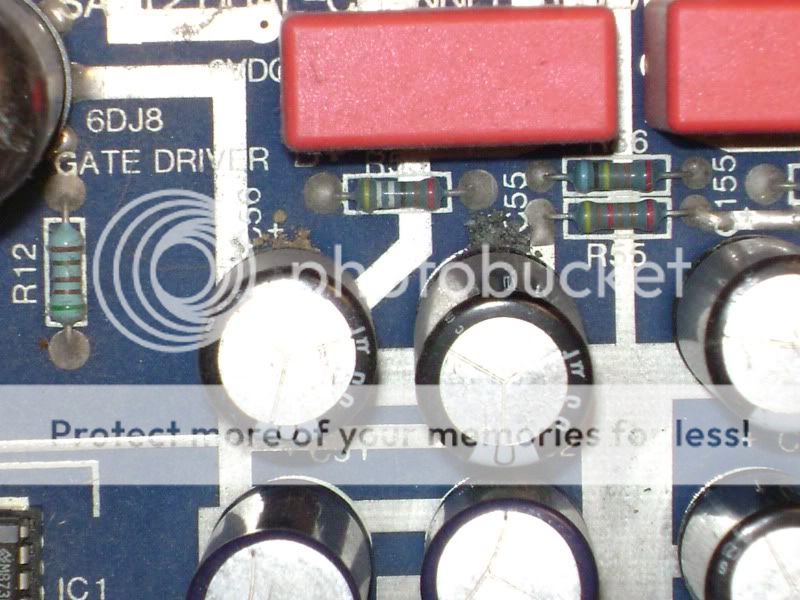
Ohhhhh...so THAT's what a leaky cap looks like???
I've done the reading as best as I can on this one. Been to Michael Elliot's website many times and searched the threads etc. etc. I've been paranoid for a while I guess, even though my time with this amp has been wonderful up until now. I picked it up about 4 years ago for $500 to my door.
What I'm looking for is some input from the experts as to whether this is definitely a blown output stage, and if so what I should do about it. Is there a SIMPLE way to take measurements with a multi-meter and confirm the damage?
The circumstances of the incident were as follows:
1- Watching a movie...wanted better audio, decided to turn on stereo which I have hooked up to the DVD player.
2- Preamp clicks on...wait 15 or so sec, turn on amp.
3- Amp light cycles green after warmup...release mute on preamp and adjusted levels.
4- Sound is normal...turn to walk away...What's that smell?!!!...Sniff Sniff...is it coming from the cabinet?...a few seconds of uncertainty...mute preamp...shut off amp...shut off preamp.
The sound was still playing from the system when I decided to shut it down. I initially thought the smell was coming from my Audible Illusions preamp, so I cracked it open first. No obvious signs, so I pulled the amp and that was that.
One thing that I am regretting is the fact that I was recently testing some Rotel amps I acquired for a dedicated HT system through the same speakers. I neglected to disconnect the speaker cables running from one of the Rotel amps. I'm wondering if it is possible that the additional cabling and connection added resistance that caused the damage. The speakers used are my old KEF 104/2s that present a 4 Ohm load. None of the wiring appeared to be shorted out, but I am wondering if this happened due to my stupidity.
Assuming the output stage is shot, I'd like some input as to some options I've looked into as far as fixing the amp. Alta Vista is NOT an option as far as upgrades are concerned. I don't have a very good feeling about his used Mosfet's that he pulls from the units he upgrades either, especially considering the $220 he wants for the parts alone and the fact that I may just be setting myself up for another failure even if I could pull off the install. Paying someone else is questionable, even if I could find someone locally whose skills I trust I doubt I could afford it. I have read the information on Elliot's site and a few threads on here concerning the possibility of using Exicon Mosfets as a replacement in the output stage. I happened to find this a few months ago for sale on ebay...

and this...

...which I suppose could be used to address the fact that the power supply has leaky caps.
They seem like a reputable company. I have spent some time on their website, and they offer these as DIY kits and other services including install of these products and a complete overhaul option with other upgrades included...not that it is an option for me financially.
I have contacted them to see if these products would work in my SA12, and I was told they would because the SA12 and SA100 share the same circuit.
My dilemma is this, my skills with electronics are VERY few, and my resources are limited. I still have a pair of ASL Wave 8s sitting on the shelf downstairs because I couldn't solve a humming problem with one of them after an extensive thread of feedback on here a few years ago.
I can follow instructions if they are detailed and I have the required tools. The documentation on these products seems pretty extensive, although it would appear I would have to buy or borrow some tools I have never used such as a variac etc. in order to complete the installation properly.
I love this amp, and I am very sad that it appears that it is more than likely toast right now. I'd like to fix it affordably somehow, and these kits seem like the closest I might get to that goal unless someone else on here thinks we could put together a parts list and a how to that would use these kits as a model for repairing these amps? Thanks.
Kevin
This is what I found last night after pulling my Counterpoint amp out of the cabinet and opening it up for a look...toasty resistors on the output stage of the left channel. I also found this...
Ohhhhh...so THAT's what a leaky cap looks like???
I've done the reading as best as I can on this one. Been to Michael Elliot's website many times and searched the threads etc. etc. I've been paranoid for a while I guess, even though my time with this amp has been wonderful up until now. I picked it up about 4 years ago for $500 to my door.
What I'm looking for is some input from the experts as to whether this is definitely a blown output stage, and if so what I should do about it. Is there a SIMPLE way to take measurements with a multi-meter and confirm the damage?
The circumstances of the incident were as follows:
1- Watching a movie...wanted better audio, decided to turn on stereo which I have hooked up to the DVD player.
2- Preamp clicks on...wait 15 or so sec, turn on amp.
3- Amp light cycles green after warmup...release mute on preamp and adjusted levels.
4- Sound is normal...turn to walk away...What's that smell?!!!...Sniff Sniff...is it coming from the cabinet?...a few seconds of uncertainty...mute preamp...shut off amp...shut off preamp.
The sound was still playing from the system when I decided to shut it down. I initially thought the smell was coming from my Audible Illusions preamp, so I cracked it open first. No obvious signs, so I pulled the amp and that was that.
One thing that I am regretting is the fact that I was recently testing some Rotel amps I acquired for a dedicated HT system through the same speakers. I neglected to disconnect the speaker cables running from one of the Rotel amps. I'm wondering if it is possible that the additional cabling and connection added resistance that caused the damage. The speakers used are my old KEF 104/2s that present a 4 Ohm load. None of the wiring appeared to be shorted out, but I am wondering if this happened due to my stupidity.
Assuming the output stage is shot, I'd like some input as to some options I've looked into as far as fixing the amp. Alta Vista is NOT an option as far as upgrades are concerned. I don't have a very good feeling about his used Mosfet's that he pulls from the units he upgrades either, especially considering the $220 he wants for the parts alone and the fact that I may just be setting myself up for another failure even if I could pull off the install. Paying someone else is questionable, even if I could find someone locally whose skills I trust I doubt I could afford it. I have read the information on Elliot's site and a few threads on here concerning the possibility of using Exicon Mosfets as a replacement in the output stage. I happened to find this a few months ago for sale on ebay...
and this...
...which I suppose could be used to address the fact that the power supply has leaky caps.
They seem like a reputable company. I have spent some time on their website, and they offer these as DIY kits and other services including install of these products and a complete overhaul option with other upgrades included...not that it is an option for me financially.
I have contacted them to see if these products would work in my SA12, and I was told they would because the SA12 and SA100 share the same circuit.
My dilemma is this, my skills with electronics are VERY few, and my resources are limited. I still have a pair of ASL Wave 8s sitting on the shelf downstairs because I couldn't solve a humming problem with one of them after an extensive thread of feedback on here a few years ago.
I can follow instructions if they are detailed and I have the required tools. The documentation on these products seems pretty extensive, although it would appear I would have to buy or borrow some tools I have never used such as a variac etc. in order to complete the installation properly.
I love this amp, and I am very sad that it appears that it is more than likely toast right now. I'd like to fix it affordably somehow, and these kits seem like the closest I might get to that goal unless someone else on here thinks we could put together a parts list and a how to that would use these kits as a model for repairing these amps? Thanks.
Kevin
Hi,
The leak of these capacitors is very common, I had a SA100 and changed them. If your mosfets has died, you only have two options, or get these pulled from other SA12/100 or buy a kit with new circuit.
This eBay circuit have a nice looking, the Altavista kit is a complete and different amplifier, much better than the original but costly (I mounted this kit in my SA100)(Is the same circuit as the Aria amp).
Good luck!
One thing that I am regretting is the fact that I was recently testing some Rotel amps I acquired for a dedicated HT system through the same speakers. I neglected to disconnect the speaker cables running from one of the Rotel amps. I'm wondering if it is possible that the additional cabling and connection added resistance that caused the damage.
Kevin
Hi Kevin
Thats the reason you have toasted your mosfets output stage. You had two amps outputs connected together, via the speaker binding posts.
Amps hate that...
")
Hi Kevin
Thats the reason you have toasted your mosfets output stage. You had two amps outputs connected together, via the speaker binding posts.
Amps hate that...
Just to clarify...I didn't actually have two running amplifiers connected to the same set of speakers. I simply forgot to disconnect the cables that I ran to the speakers from the second Rotel amp. Whether or not that makes any difference is irrelevant...same outcome I suppose.
I would still like to find a way to confirm the damage and have been reading some of the information related to the installation of the replacement Mosfet kits. They're start up and biasing procedure jolted my memory of a statement I came across on the Alta Vista site related to voltage at the speaker terminals indicating a blown output stage.
From Greenstreet:
"If the DC offset is more than 5 volts, it indicates a fault in the wiring
and the problem must be corrected before continuing. The DC offset will bounce around quite a bit and never truly settle down to a steady measurement, so donʼt panic."
I'm wondering if this is the way to go about confirming the damage?
This is what I sw on Alta Vista:
"On Counterpoint SA-type amplifiers, an output stage that has failed is indicated by a large DC offset at the speaker terminals and fused gate resistors on the MOSFET sockets. Shorted speaker wires is the main cause of such a failure: the high internal losses of the MOSFETs pretty much guarantees that they will fail when their current limits have been exceeded.
Final failure of the entire output stage typically occurs at the next turning-on of the amplifier, when the weak device exhibits a drain-to-gate short. This causes full drain voltage to appear on the gate drive lines, which fuses the gate protection Zener diodes and gate resistors. On some occasions, the muting relay may also be fused, causing the gate drive lines to be shorted to ground. Replacement of all eight MOSFETs per channel (SA-20/220) or all four MOSFETs per channel (SA-12/100), all gate resistors, all four protection diodes and (rarely) the muting relay is indicated."
Last edited:
The burnt gate resistors are proof enough that the associated MOSFET is fried. These are 1/2 watt resistors and by the time that they have smoked the MOSFET is well and truly deceasedI would still like to find a way to confirm the damage
Unfortunately, not a good combination for a tricky amp with expensive bits to replace. Although these amps were quite reliable, you would be working on a 22+ year old piece of kit.My dilemma is this, my skills with electronics are VERY few, and my resources are limited.
Thanks for chiming in Alan. I was afraid that was the case.
Well, perhaps I can figure a way to afford one of these mosfet output kits from GreenStreet.
I have been reviewing the install documentation and I am impressed with the detail. I'm fairly confident if I pick up an inexpensive variac off of ebay as they suggest and the few other items I don't have I would be able to pull it off with some patience.
As far as the power supply is concerned, perhaps I'll just replace the old leaky caps for now...assuming that will save me a bit over the $175 they want for their refurb kit.
Hi, yeah, I had the same experience with my SA-12 just a few months ago. Here's a thread related to that. I see the gate resistor on your amp is burnt. That happens when the MOSFETs die since the drain usually fuses to the gate. That results in DC at the output, and the DC killed one my DIY speakers. I measure like 45 volts DC at the output.
HTGuide Forum - Counterpoint Amp Repair
On turn on there is a relay that shorts the gate resistor to ground to stop turn on thump and let the tubes warm up. So, those gate resistors are then dissipating a whole lot of power, hence the smoke and smell from burnt resistors.
I haven't fixed it yet, but eventually I plan on doing my own output stage. Not sure what transistor to use though. Eliot used carefully matched transistors that were thermally stable, and are not longer available.
I was thinking about paralleling 4 matched pairs (4 p-channels, 4 n-channels) IRF520/IRF9520 with a small source resistance like 0.22 ohms. This would keep the output impedance low, cause Elliot didn't use any feedback on the output stage, so the damping factor would be quite low if using just 2 pairs of output transistors with the added source resistors. I think that would work but, not sure until I try.
Probably other and maybe better combinations to try on the output stage. I was just trying to keep the capacitance and transconductance figures on par or better that Elliot's output stage.
Anyway, good luck with fixing the amp.
Hi chromenuts,
Looking at the picture there, it doesn't look like those gate resistors are really toasted as I've seen them in the past. At this point, I would just stop and do some investigating.
You need a half decent meter, digital preferred. Check to ensure the filter capacitors are discharged so you don't get a nasty surprise. The next step is super simple, check the speaker fuses, they should have blueish plastic covers over them. Make sure both fuses are good for the next test, remove anything you had to change when you're done the next step. Stick a meter probe into the red speaker jack, then set your meter to resistance function and touch the filter capacitor for each supply polarity, one positive and the other negative. Also, check to the ground (the connection to both capacitors). You should read really high resistance for all tests. Let us know what you get. Also, if you measure the ground connection (same one you just probed) and move the probe from the speaker jack to each side of the discoloured resistors, you should measure a very low resistance (a short, depending on how good the probes are). Again, let us know what you find.
Without knowing exactly what that new assembly you found on Ebay is (a schematic with values), I wouldn't touch it for love nor money. The original designer isn't an option either - unfortunately. Alan is extremely knowledgeable on these amplifiers, and I do have a fair amount of experience with them as well. Understand that there are two different basic versions of the driver section (the last tube). The really good news is that with lower supply voltages, your version is far more reliable than the SA-100. This matters. Be aware that there are design choices made on the main PCB that impede the sound quality as it sits as well. I've been redesigning it, but I'm not ready yet. The improvements in sound are already pretty stunning, while retaining the characteristic sound of Counterpoint. That's the hard part when redesigning something.
-Chris
First off...thanks once again for taking the time to offer any guidance and feedback. That goes out to all you guys....it is really appreciated.
You need a half decent meter, digital preferred.
OK...well all I have to work with is your standard run of the mill Craftsman digital multi meter that I use for working on cars and what not...still it should do.
Check to ensure the filter capacitors are discharged so you don't get a nasty surprise.
Yup...made a discharging rig for the caps on the amps I was trying to fix a few years back.
The next step is super simple, check the speaker fuses, they should have blueish plastic covers over them.
Checked every fuse on the board with the tester for continuity...all good.
Make sure both fuses are good for the next test, remove anything you had to change when you're done the next step. Stick a meter probe into the red speaker jack, then set your meter to resistance function and touch the filter capacitor for each supply polarity, one positive and the other negative.
OK...the left channel (with the burnt resistors) shows nothing ( I set the tester to 2000K Ohms) to either polarity on both caps. Did the same test (on the same setting) to the right channel for both caps and I show about 350 across the board.
Also, check to the ground (the connection to both capacitors). You should read really high resistance for all tests.
Same results as above. Nothing to the grounds on the left channel with toasted resistors and 350 to all ground points when checking the right channel.
Let us know what you get. Also, if you measure the ground connection (same one you just probed) and move the probe from the speaker jack to each side of the discoloured resistors, you should measure a very low resistance (a short, depending on how good the probes are). Again, let us know what you find.
Clamped onto the ground bar of the supply caps (confirmed continuity of ground) and tested resistors. I had to adjust the tester as it seemed like it was measuring something out of the set range. The ends of the burnt resistors that are soldered to the individual Mosfets appear to have a resistance that increases (as if a capacitor or something is charging in the circuit). If I hold the probe in place it seems to level out at about 220 Ohms for this channel. The other side of the burnt resistors that are connected via the small teflon covered rail that also connects to the diodes measures about .5 Ohms. I repeated this test for the Right channel using the same scale on the meter. The side of the resistors that are connected to the Mosfets immediately shoots up to 400 Ohms with no fluctuation. The other side of the resistors are connected via the bar to the diodes measures .5 Ohms like the Left channel did.
Kevin
Hi Kevin,
Cool, thank you.
Your Sears meter will do just fine. I'm really happy that not only do you have a meter, but that you would be familiar with how it works and acts measuring various things. This makes everything much easier.
All the fuses are good, it's looking more and more like your outputs should be not shorted and may be perfectly fine. Let's hope for the best outcome here. These output mosfets require extremely close matching. That's one thing that took Counterpoint down. These amps took far too much effort to construct with this matching requirement.
The reading of "nothing" means shorted, as in zero resistance? I need to be clear on what you are seeing on the mosfet gates please. Your readings of 350, I guess that's 350 K ohms? The actual reading is less important than the fact that both channels measure similarly and that the reading is pretty high. So for the parts up to the gate resistors, the readings look to be normal. Back to the outputs ...
The readings towards the mosfet gates are normal for open gate resistors. If these go open when the amp is running, the output stage tends to draw uncontrolled current even if the output transistors (mosfets) are fine. This would tend to open one or both DC supply rail fuses - which you found to be okay. So okay, let's have a closer look a the mosfet output transistors. At this point, the mosfet gates may be more vulnerable to damage because the protection zener diodes are now isolated from the gates. For now, short the gates to the sources with clip leads or something. The source is the other terminal like the gate terminals. The drain comes off the case contact, the metal that runs up the center of the socket where the mounting screws connect. We'll get back to those in a moment. Solder 100 ohm resistors, or whatever lowish resistors you may have on hand in 1/4 watt to 2 or 3 watt sizes. All you are doing is connecting the gates back to the gate lines and their protection network in a semi-normal situation. If you happen to have the exact values, great. Tack (temporary solder connection where the leads are not bent or crimped, just soldered) them in now. With your DVM (Digital Volt-Meter) in the resistance mode still, measure the resistance between one positive drain to the negative drain on the other polarity output. This is the same as measuring the resistance across the filter capacitors from B+ to B-, except we are making sure any other open connections don't give us a false answer. Now, measure from each drain to the gate of each output. We really want to see an "open" or capacitive drift upwards in resistance.
If you feel the outputs are bad, then remove one at a time and measure between each terminal. Replace each in turn as you move on so you are sure they outputs are back in the correct locations. No need to really tighten them down, because if they are in fact good, you will need to replace the insulators and apply fresh thermal compound. You can not use the stuff they put on computer CPU chips. That stuff may be conductive (very bad in an amp). Let's hope the outputs are fine. When it comes time to do the final tightening on the output transistors, there is a specific torque to use. I can't remember the units, but it may be something along the lines of 8 in-lbs. I have a torque screwdriver I use for this purpose. Being a mechanic, I know you do understand completely this concept better than 90 % of the technicians out there. I am not pulling your leg. When reassembling any heat sink assy., everything must be very clean. Brake cleaner works well, but may remove lettering off components. It will destroy the seals on capacitors. Any no residue cleaner will work fine on the heat sink mounting surfaces. Make sure they are also flat and do not have any burrs or damaged areas. File / sand any defects flat and smooth. This tends to be hard on the black anodizing. Same thing goes for the mounting surfaces on any semiconductor packages. New grease is applied in a thin, even coat. I find a #2 artist's brush (for oil paint I think) works extremely well. Do not buy real expensive brushes.
The very low resistance reading on the gate lines is very good. That's more good news. Sometimes the relay contacts are burned open. Of course, it is also possible for the contacts to be welded closed also. We can't easily check for welded contacts until the amplifier is powered up and comes out of mute. The contacts then are supposed to release the gates from ground. By grounding the gates of the mosfets, Michael was eliminating turn on thumps as well as killing the bias current in the output stage. Not a bad idea.
Time to go play in your Counterpoint. Let us know what you find please. Keep in mind that if you need to repair this amplifier, it will cost what it costs. Getting matched parts (outputs) is required, and that may mean buying 20 or so outputs for each polarity in order to get decent matched parts. There is no other was to go about this and have the amp run properly and reliably. Other transistor types are not recommended, and the originals are still available. Buy them in 25 lot, still in their rails. Do not buy them any other way because you need to have them all from the same batch. The same silicon wafer is the only way you will get matches unless you are extremely lucky. A fool's bet in this case. This means you must buy these from an authorized dealer like Digikey. Someplace you can guarantee the parts come directly from International Rectifier. Stress this when you place your order. If you buy from somewhere for a better price, just take that money and burn it in the back yard. That is more satisfying.
A quick note. If you have a repair person who doesn't charge a lot for a really tight set of outputs, that person or place is either not matching them, or not matching them super closely - no matter what they tell you. I'm afraid the least expensive way to do this is to buy all those parts yourself. Make the matching jig up and do all the matching yourself. Once you have what you believe are a matched set, you will have to run the pair up together to ensure they are at the same temperature and check the current sharing. Don't be surprised if they aren't matched. It takes a little bit of practice to get it right. A thermocouple temperature meter is really going to help here. Hint: the readings must be taken at the same temperature and current. Yes, this is a complete PAIN in the rear end. Very time consuming even for experienced people to do.
Well, have a great evening / day tomorrow. You have my sincere wishes for an intact output stage.
-Chris
Hi John,
What Mr. Elliot is saying is pure poppycock. The only thing that is discontinued is someone hand selecting these parts at his factory. The parts are easily sourced, and if they are discontinued at some point, there are similar parts that will take their place. These are Hexfets, Lateral types will not work in this circuit without changing the bias setup. Not a bad thing and they may perform better in a properly designed output stage. Given that there is no overall feedback in the original design, you would benefit from more output devices in parallel on more than one front. Without the output stage enclosed in the feedback loop, source resistors will have a negative impact on sound quality. Of course, I'd certainly use source resistors to ease the matching requirements and add more outputs. Then I would definitely use overall negative feedback. From experience, I can tell you that the sound will only improve and distortion does drop. That's as long as you design the circuit better than it was and eliminate some other issues as well. You can retain that sound that marks the amp as a Counterpoint (I did) while really improving everything about that amplifier.
A new output stage is precisely what the SA-100 and SA-220 need to be reliable. Use the new On-Semi MJ21195 and MJ21196, or you can buy the flat pack MJL series. That way you can add more devices. Driven the way the existing output stage is, BJT stages have lower distortion. The output stage I am working on is based on a Diamond buffer and sounds exquisite. Mind you, there are several other areas that need to be addressed in order to make a clean, low distortion and stable amplifier.
I have two prototypes out in the field running for about 5 years now. I was developing these when I was involved in an accident. This completely eliminated all memories of this work and a lot of other things I knew. So from 2005 on, I have been relearning what I knew and I am about to attack my notes and physical prototype boards I have here. It's as if someone else did all this, but the notes are in my hand, and the PCBs are marked and laid out by me. Spooky and frustrating. At least they are still running fine.
For what it's worth to you, the BJT stage sounds far better than the original mosfet stage. Both amps have identical, modified voltage amp sections and only differ in the output stage alone. There is no contest here, and SY (another moderator) heard these two amps, as well as an original kept as a reference. He expressed a very clear preference for the BJT stage. There are still a few issues to deal with performance-wise, but the basic topology is solid.
The original design does have feedback from the voltage amp stage output back to the first amp stage. It may be unintentional, but there is feedback through the lower 6922 section to the cathode of the first gain stage. The lower 6922 section is acting as an extremely non-linear feedback resistor. It ain't pretty. One of the first modifications I made was to eliminate this loop. That gave rise to other problems, and then still more until I reached his first error. After that, no more surprises and everything improved as each design goof was "repaired". I use active current sources in my diamond buffers instead of resistors. That helps as well.
I'd say you were on the right track. Keep it up and continue along that same path! Keep in mind that an SA-100 has more troubles, so it is actually less desirable. I'll say the same thing about the SA-220 as well. Just don't believe much of what you hear / read from Mr. Elliot's web site or other posts out there.
-Chris
The reading of "nothing" means shorted, as in zero resistance?
Yes...nothing registered on any of the resistance scales on my meter.
I need to be clear on what you are seeing on the mosfet gates please. Your readings of 350, I guess that's 350 K ohms?
Yes to 350K Ohms...However, this measurement was NOT at the Mosfets...it was the resistance I measured between the positive speaker terminal of the channel with undamaged Mosfet resistors and the power supply cap terminals and ground points you mentioned.
The actual reading is less important than the fact that both channels measure similarly and that the reading is pretty high.
I don't believe that was the case. Perhaps I worded things poorly. I tried to say that the measurements of the two channels were completely different. Where the resistors connect to the Mosfets in the output stages the channel with burnt resistors when probed gradually increases in resistance (as if something is charging in the circuit) until it reached about 220 Ohms. The other channel with undamaged resistors reads 400 Ohms as soon as it is probed were the resistors connect to its Mosfet. The only common measurement to both channels is at the other end of these resistors where they connect to the teflon covered rail that runs up to the diodes mounted over the Mosfets. Both channels measure .3 Ohms at this point.
So for the parts up to the gate resistors, the readings look to be normal. Back to the outputs ...
Are they???...or did we misunderstand one another? What you go on to request from this point in your post will be very difficult for me to follow without me posting up some Photoshop pics with notes so I can be clear on what you are requesting I do. I'm not sure what's needed next.
Kevin
I reread your post a few times and stuck my head back in the case for a look. I think it is pretty clear to me now what you want. For ultimate clarity I decided to make this labeled image up and post a list showing my understanding.
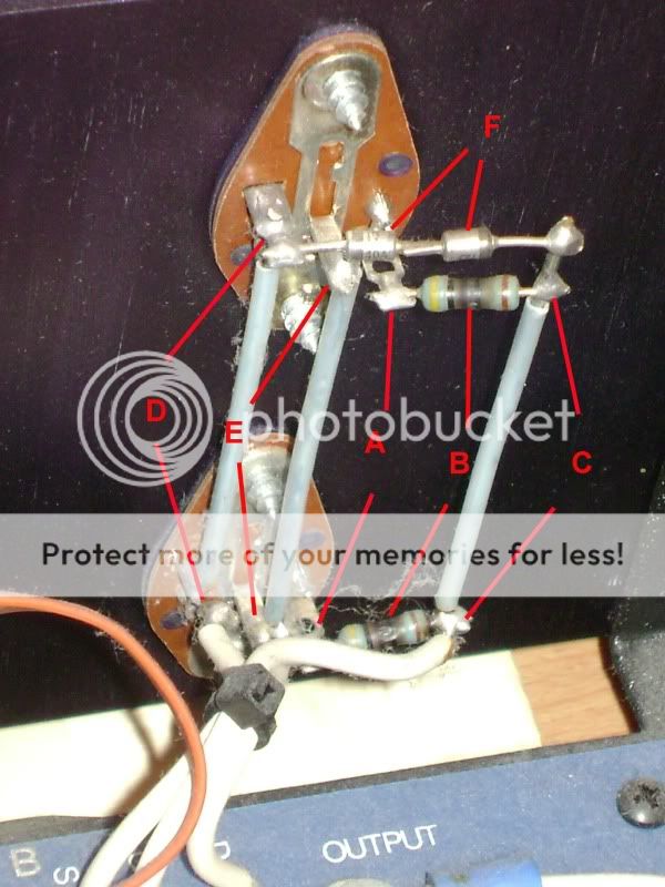
OK ...so this became more obvious to me when I traced the white wires coming off of the Mosfet back to the circuit board and I found them connected to tabs labeled D, G and S or Drain, Gate and Source. So my rundown for the diagram is as follows:
A- Gate connections
B- Gate resistors
C- Not sure of the term for this. It ultimately facilitates the gate's connection to the circuit board and allows for the resistors and diodes to be arranged in a protection circuit?
D- Source connections
E- Drain connections
F- Zener diodes
If you need me to, I can re-list my measurements taken for both channels on the amp and reference them to this image. But in the mean time...
...let's have a closer look a the mosfet output transistors. At this point, the mosfet gates may be more vulnerable to damage because the protection zener diodes are now isolated from the gates. For now, short the gates to the sources with clip leads or something. The source is the other terminal like the gate terminals.
I will take some lines I have made up with aligator clips on both ends and run them from the "A" points in the diagram to the "D" points for both Mosfets in that channel.
The drain comes off the case contact, the metal that runs up the center of the socket where the mounting screws connect. We'll get back to those in a moment. Solder 100 ohm resistors, or whatever lowish resistors you may have on hand in 1/4 watt to 2 or 3 watt sizes. All you are doing is connecting the gates back to the gate lines and their protection network in a semi-normal situation. If you happen to have the exact values, great. Tack (temporary solder connection where the leads are not bent or crimped, just soldered) them in now.
OK...I'm going to tack some new resistors across the resistors labeled "B" in the diagram with some Ratshack 1/4 watt (5%) 100 Ohm resistors I have in hand.
With your DVM (Digital Volt-Meter) in the resistance mode still, measure the resistance between one positive drain to the negative drain on the other polarity output.
Are you saying I should measure resistance between the drain on the pair of Mosfets connected to the board at the tabs labeled "P-type" and the drain on the other pair connected to the board at the tabs labeled "n-type" for the channel I am working on?
This is the same as measuring the resistance across the filter capacitors from B+ to B-, except we are making sure any other open connections don't give us a false answer. Now, measure from each drain to the gate of each output. We really want to see an "open" or capacitive drift upwards in resistance.
OK...this is pretty straight forward. If you can just confirm my understanding of the previous request, I will get this data and post it as soon as I have installed the new resistors properly and can take the measurements. Thanks.
Kevin
Update
OK...well I started trying to put some new resistors in place.
This is like mission impossible...there is NO room in there for me to manipulate tools with my big clumsy hands. Getting the alligator clips in place on the gate and source tabs was a chore as it was.
It was immediately obvious that I could NOT even attempt to place a resistor with the originals still in place. So after a bit of a struggle, and some melted insulation on the gate lead wire, I pulled the original resistors out.
I decided to take a breath, and in the meantime I measured resistance on the toasted resistors that I pulled. Instead of getting nothing across them as I expected, I get a consistent 384 Ohms on both. Does this mean the protection circuit was still intact and that the Mosfets are definitely fried? Or should I proceed in putting new resistors in place and do the other tests you asked for? I have a small bin of resistors and probably have something almost identical to what I measured...like at 390 Ohms.
Kevin
OK...well I started trying to put some new resistors in place.
This is like mission impossible...there is NO room in there for me to manipulate tools with my big clumsy hands. Getting the alligator clips in place on the gate and source tabs was a chore as it was.
It was immediately obvious that I could NOT even attempt to place a resistor with the originals still in place. So after a bit of a struggle, and some melted insulation on the gate lead wire
, I pulled the original resistors out. I decided to take a breath, and in the meantime I measured resistance on the toasted resistors that I pulled. Instead of getting nothing across them as I expected, I get a consistent 384 Ohms on both. Does this mean the protection circuit was still intact and that the Mosfets are definitely fried? Or should I proceed in putting new resistors in place and do the other tests you asked for? I have a small bin of resistors and probably have something almost identical to what I measured...like at 390 Ohms.
Kevin
anatech said:Hi John,
What Mr. Elliot is saying is pure poppycock. The only thing that is discontinued is someone hand selecting these parts at his factory. The parts are easily sourced, and if they are discontinued at some point, there are similar parts that will take their place.
Hi, Chris,
Yes awhile back I did find some replacements but they were hard to find and they wanted $32.00 apiece. Like you say, matching them would like impossible especially at that price. But, I'm sure you know where they can be source from.
Anyway, what do you think of my IRF520/IRF9520 solution? I would be using twice the number of output devices Mr. Elliot used, matched with 0.22 added source resistors to each device.
I don't understand the benefit of using lateral mosfets in this. Doesn't mean there isn't one. But laterals have a high output impedance and, at least the with the laterals I looked at, the capacitance is higher than 2 of the IRF520 parts in parallel.
Having a high output impedance would kill the damping factor on this, since it uses no feedback on the output stage.
I think I'm just going to go with hexfet replacements and not go the Green Street route.
chromenuts said:I get a consistent 384 Ohms on both.
My resistors are fried significantly more that yours. They measure 515 and 480 ohms probably because of the damage.
Your Sears meter will do just fine. Chris
Almost any meter will suffice for servicing these amps. This, like most audio amps, is not a piece of instrumentation. But you will benefit from having at least two. I use two but have the mains voltage and current on meters.
A variac and dummy speaker loads are important.
A signal source (does not need to be low distortion - a function generator will suffice) plus scope is needed. To really see what is happening in a common-drain MOSFET output stage you want 200MHz bandwidth and the more the merrier. But you can get away with much less if you succumb to a little blind faith.
I have a small bin of resistors and probably have something almost identical to what I measured...like at 390 Ohms. Kevin
The gate resistors differ for the rear (NMOS) and front (PMOS) pairs. The rear gate resistors should be 422 Ohms and the front gate resistors should be 165 Ohms. Or thereabouts. These values are based on the typical characteristics of the original MOSFETs which were from Harris. So you may have those MOSFETs and your particular transistors may have the actual measurements designed for.
It would be worth popping the black plastic cover off one of the MOSFETs to see what you have "under the hood".
I don't understand the benefit of using lateral mosfets in this. Doesn't mean there isn't one. But laterals have a high output impedance and, at least the with the laterals I looked at, the capacitance is higher than 2 of the IRF520 parts in parallel. Johnloudb
The sole benefit of lateral MOSFETs in this situation is that you can buy them. A benefit that should not be sniffed at, by the way. Then the rationalizations start. But I see you want to bring engineering into it - didn't you realize this is diyaudio? tsk tsk.
anatech said:I have two prototypes out in the field running for about 5 years now. I was developing these when I was involved in an accident. This completely eliminated all memories of this work and a lot of other things I knew. So from 2005 on, I have been relearning what I knew and I am about to attack my notes and physical prototype boards I have here. It's as if someone else did all this, but the notes are in my hand, and the PCBs are marked and laid out by me. Spooky and frustrating. At least they are still running fine.
Hi Chris, ignore my last post. I feel like an idiot - I hadn't fully read your last post, and missed a lot. I seem to have a habit of doing that. Thanks for the input!
I'll check out the BJT's you mentioned. Sorry to hear about your accident. I was hit broadside by a semi-truck long a ago while making a left turn out in the Neveda desert. I have no memory of what happened 1 hour after the wreck, though my dad tells me I was never unconscious and was talking during that time. So, I have a slight hint of how you feel.
anatech said:I'd say you were on the right track. Keep it up and continue along that same path! Keep in mind that an SA-100 has more troubles, so it is actually less desirable. I'll say the same thing about the SA-220 as well. Just don't believe much of what you hear / read from Mr. Elliot's web site or other posts out there.
-Chris
I have have the SA-12, it was supposed to be upgraded but they never did the upgrade that I can tell, and they didn't charge us for it. Long story. But it's an SA-12 board. Glad to know I'm on the right track.
VivaVee said:The sole benefit of lateral MOSFETs in this situation is that you can buy them. A benefit that should not be sniffed at, by the way. Then the rationalizations start. But I see you want to bring engineering into it - didn't you realize this is diyaudio? tsk tsk.
Ha, Ha, ... but my favorite amp that I've owned is a Dreadnaught 500, damping factor of 1000. I don't want a Mary had a little lamb amp.
I like the Rutger Hauer amps.
The Counterpoint isn't that, but I'll take it in that direction. I need an amp that will drive a real speaker.
Attachments


- Home
- Amplifiers
- Solid State
- Counterpoint SA12: What's that smell?