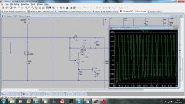
Here is a simulation with mosfet "beta enhancer". I used NDC7002N from LTspice libtary, as NTX model gives someting worst distortions:
Fourier components of V(vout)
DC component:0.0191634
Harmonic Frequency Fourier Normalized Phase Normalized
Number [Hz] Component Component [degree] Phase [deg]
1 1.000e+03 2.192e+01 1.000e+00 -0.13° 0.00°
2 2.000e+03 5.169e-06 2.358e-07 85.63° 85.75°
3 3.000e+03 6.423e-06 2.931e-07 24.43° 24.56°
4 4.000e+03 4.998e-07 2.280e-08 98.30° 98.43°
5 5.000e+03 8.192e-07 3.737e-08 13.62° 13.75°
6 6.000e+03 2.665e-07 1.216e-08 79.89° 80.02°
7 7.000e+03 9.082e-07 4.144e-08 23.05° 23.18°
8 8.000e+03 2.407e-07 1.098e-08 25.16° 25.29°
9 9.000e+03 7.176e-07 3.274e-08 22.85° 22.98°
Total Harmonic Distortion: 0.000038%
Fourier components of V(vout)
DC component:0.0191534
Harmonic Frequency Fourier Normalized Phase Normalized
Number [Hz] Component Component [degree] Phase [deg]
1 2.000e+04 2.190e+01 1.000e+00 -2.55° 0.00°
2 4.000e+04 3.065e-05 1.399e-06 -46.50° -43.95°
3 6.000e+04 6.260e-05 2.858e-06 131.10° 133.65°
4 8.000e+04 1.819e-05 8.305e-07 -49.44° -46.89°
5 1.000e+05 2.623e-05 1.197e-06 166.49° 169.04°
6 1.200e+05 1.922e-05 8.773e-07 -51.09° -48.55°
7 1.400e+05 4.417e-05 2.016e-06 165.38° 167.92°
8 1.600e+05 1.480e-05 6.755e-07 -54.60° -52.05°
9 1.800e+05 4.556e-05 2.080e-06 168.25° 170.80°
Total Harmonic Distortion: 0.000468%
I don't see a reason to use MOSFET here as a small BJT is good enough.
dado
Fourier components of V(vout)
DC component:0.0191634
Harmonic Frequency Fourier Normalized Phase Normalized
Number [Hz] Component Component [degree] Phase [deg]
1 1.000e+03 2.192e+01 1.000e+00 -0.13° 0.00°
2 2.000e+03 5.169e-06 2.358e-07 85.63° 85.75°
3 3.000e+03 6.423e-06 2.931e-07 24.43° 24.56°
4 4.000e+03 4.998e-07 2.280e-08 98.30° 98.43°
5 5.000e+03 8.192e-07 3.737e-08 13.62° 13.75°
6 6.000e+03 2.665e-07 1.216e-08 79.89° 80.02°
7 7.000e+03 9.082e-07 4.144e-08 23.05° 23.18°
8 8.000e+03 2.407e-07 1.098e-08 25.16° 25.29°
9 9.000e+03 7.176e-07 3.274e-08 22.85° 22.98°
Total Harmonic Distortion: 0.000038%
Fourier components of V(vout)
DC component:0.0191534
Harmonic Frequency Fourier Normalized Phase Normalized
Number [Hz] Component Component [degree] Phase [deg]
1 2.000e+04 2.190e+01 1.000e+00 -2.55° 0.00°
2 4.000e+04 3.065e-05 1.399e-06 -46.50° -43.95°
3 6.000e+04 6.260e-05 2.858e-06 131.10° 133.65°
4 8.000e+04 1.819e-05 8.305e-07 -49.44° -46.89°
5 1.000e+05 2.623e-05 1.197e-06 166.49° 169.04°
6 1.200e+05 1.922e-05 8.773e-07 -51.09° -48.55°
7 1.400e+05 4.417e-05 2.016e-06 165.38° 167.92°
8 1.600e+05 1.480e-05 6.755e-07 -54.60° -52.05°
9 1.800e+05 4.556e-05 2.080e-06 168.25° 170.80°
Total Harmonic Distortion: 0.000468%
I don't see a reason to use MOSFET here as a small BJT is good enough.
dado
Is that a bad thing ? Is it something that can be heard ?
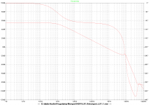
(below 1 ) is the "base" thread topic amp. Not bad - a PPM amp. Besides what a bootstrap does in feeding back EMF in a local loop back to the voltage stage , a bootstrapped amp will only slightly deviate from it's current sourced "cousin" - both will simulate nearly the same and just sound slightly different.
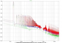
(below 2 ) is the "harmonic killer" 😱 I was surprised at it , even. With just half the loop gain , it blows the lin amp away. So I built one (I actually just needed a subwoofer amp). Hooking it to a full range speaker convinced me it had some real possibilities. Cascodes and the reduction of the early effect DO make for better sound , the simulations (first watt - class A) show the VAS itself is nearly distortionless , even compared to the LIN circuit. In both simulations ,the higher power FFT's just show the contributed Xover distortion differences between a EF2 and 3. The VAS itself, in the cascoded version, still shows much better linearity.
Both simulations were done with Cordell defined models (no OEM supplied ones) , 4R , 3 pair-mjl 1302/4281 op @ 85ma bias.
I did the "no - no" homemodder mentioned 🙁 , and ran a cascoded VAS on a EF2 (for 6 month's). It's sound was good at low levels but quite poor at higher levels. All this fooling around paid off - have you ever tried to modulate the impedance of the cascodes with a bootstrap ? The downside of this route is the ever increasing complexity (more parts)... quite the compromise. 😀
OS
OS, do I do OLG diagram correctly(I suppose that you are talkink about LX1.1) from your sim page?? Quite low OLG. I changed 2SA1381/2SC3502 to KSA/KSC as I don't have those spice models.
dado
Attachments
I'm afraid if people keep coining new acronyms instead of using accepted circuit descriptions, preferably with circuit diagrams discussion will become completely indecipherable
and I encourage putting the actual img in the post post - I certainly skip over .pdf or .zip attachments unless really strongly motivated
VAS input buffer, “beta enhancer” seems unambiguous
Cascodes have a few variations that may not have good nomenclature to distinguish them
Pass, Hawksford have described the advantages of a cascode that returns the upper/”cascode” Q base current to the lower/“control” Q emitter – in the VAS this requires VAS degeneration R
http://www.essex.ac.uk/csee/research/audio_lab/malcolmspubdocs/J10 Enhanced cascode.pdf
Self, Cordell both use VAS degeneration – although the reason given is for current sense/clamping
Cherry has suggested the VAS degeneration has little cost but gives some stability advantage
yes , you do.
Here they are (attached) , more realistic model's.
OS
Simulation with ksa1381/ksc3503 models from mongrelmodels file shows drastic difference to 2sa1381/2sc3503 more realistic models. Daos that mean ksa/ksc are not reliable models?
First FFT is with 2sa/2sc models.
dado
Attachments

Is that a bad thing ? Is it something that can be heard ?
(below 1 ) is the "base" thread topic amp. Not bad - a PPM amp. Besides what a bootstrap does in feeding back EMF in a local loop back to the voltage stage , a bootstrapped amp will only slightly deviate from it's current sourced "cousin" - both will simulate nearly the same and just sound slightly different.
(below 2 ) is the "harmonic killer" 😱 I was surprised at it , even. With just half the loop gain , it blows the lin amp away. So I built one (I actually just needed a subwoofer amp). Hooking it to a full range speaker convinced me it had some real possibilities. Cascodes and the reduction of the early effect DO make for better sound , the simulations (first watt - class A) show the VAS itself is nearly distortionless , even compared to the LIN circuit. In both simulations ,the higher power FFT's just show the contributed Xover distortion differences between a EF2 and 3. The VAS itself, in the cascoded version, still shows much better linearity.
Both simulations were done with Cordell defined models (no OEM supplied ones) , 4R , 3 pair-mjl 1302/4281 op @ 85ma bias.
I did the "no - no" homemodder mentioned 🙁 , and ran a cascoded VAS on a EF2 (for 6 month's). It's sound was good at low levels but quite poor at higher levels. All this fooling around paid off - have you ever tried to modulate the impedance of the cascodes with a bootstrap ? The downside of this route is the ever increasing complexity (more parts)... quite the compromise. 😀
OS
Os Is the second pic the performance of the Luxman clone amp ??, that looks pretty good.
Member
Joined 2009
Paid Member
“beta enhancer” seems unambiguous
Beta is the gradient of a curve, of input base current verses output collector-emitter current of a device. It's just a measure of the input impedance of a bipolar device and it's a curve not a scalar quantity. Why is it called a beta enhancer instead of buffered VAS ?
"buffered VAS" requires additional disambiguation - you can buffer the input or output - both discussed by Self
"Darlington VAS" has been used as a name except an objection can be made that "Darlington" is usually accepted as meaning both of the collectors are connected as a 3 terminal composite Q and strictly shouldn't be used for series discrete emitter followers
"beta enhancer" can be viewed as referring to a really simple "VAS" model - that the diff pair/mirror output current is multiplied by the (bjt) "beta" and then flows in the local compensation feedback&output Z
sometimes names just become accepted even when strict syntactical analysis makes another option more sensible
but "harmonic killer" really has no accepted meaning - apparently referring to cascode above?
Member
Joined 2009
Paid Member
Os Is the second pic the performance of the Luxman clone amp ??, that looks pretty good.
Yup , that's the luxman. green LED's and all. I have the prototype running my sub now. I will show the full stereo version in "solid state picture" soon. 🙂
2 led ccs's , exotic ?? The diamond triple is both more oscillation proof and thermally stabilizes better. Just 2 semi's , 2 led's and a resistor. Pre-driver/driver Vbe totally cancels out.No nead for some exotic circuit.
Dadod , you realize - we are in Halcro territory now ! (sub PPM)
OS
Last edited:
but "harmonic killer" really has no accepted meaning - apparently referring to cascode above?
So stiff
 , that was Dadod's original term. I just referenced that to the luxman as that seemed to describe the effect of the cascode. If we can not have fun on the forum without too much confusion , what is the point ?
As a reference , the subjective banter on most of this forum really has no meaning either - except to those generating it (or profiting off of it. 😀 )
OS
Yup , that's the luxman. green LED's and all. I have the prototype running my sub now. I will show the full stereo version in "solid state picture" soon. 🙂
2 led ccs's , exotic ?? The diamond triple is both more oscillation proof and thermally stabilizes better. Just 2 semi's , 2 led's and a resistor. Pre-driver/driver Vbe totally cancels out.
Dadod , you realize - we are in Halcro territory now ! (sub PPM)
OS
I was not referring to your circuit,
dado
Hey , Dadod ... Carlos (DX) is now doing the CCS + bootstrap on his new precision 3. His just uses a BJT CCS , but it is fully functional.
OS
OS
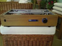
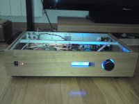
Here are some more photos.
R88 was increased in value(from 33R to 68R) as the drivers were a bit to hot for my taste. Now driver current was set to 20mA. I did not hear any difference in the sound quality.
I will not change anything any more and this is simple stable excellent sounding amp.
dado
R88 was increased in value(from 33R to 68R) as the drivers were a bit to hot for my taste. Now driver current was set to 20mA. I did not hear any difference in the sound quality.
I will not change anything any more and this is simple stable excellent sounding amp.
dado
Attachments

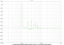
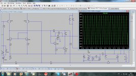
I noticed strange behavior durin simulation with 20Hz close to clipping.
The reson was in capacitance multipliers. I changed R26, R29 from 1kohm to 100ohm and R27, R28 from 33kohm to 10kohm and all was OK after that.
It looks that the capacitors connected to multiplying trensistors were loaded to slowly trough 1kohm. That manifested itself only at very low frequencies.
First diagram is with old multipliers.
dado
I was wrong regarding the reason for this behavior. It is not capacitance multiplier but to small value of the protecting resistor(R19) in preVAS emitter follower(Q7) collector. With incresed value from 220ohm to 1kohm all was OK even with original capacitance multiplier.
Be aver of this resistor as 220 ohm is not enough to protect Q7 to be burnt in the case of clipping.
1 - to small resistor
2 - increased to 1K
dado
Attachments
Many opinions.....
Yours = increase VAS ef resistor to 1k
mine = tested with 2sa992 +2sa1381 / 220R , warm 992 at clipping + no CRO errata.
Cordell = add a third transistor to shunt the ef at clip.
DX= use a larger EF device.
I like the higher value resistance method. I might change DIYA amp to at least 470R even as 220R works at 45V supplies.
Other methods are either overkill - "sonickill" or just plain silly. 😀
OS
I was wrong regarding the reason for this behavior. It is not capacitance multiplier but to small value of the protecting resistor(R19) in preVAS emitter follower(Q7) collector. With incresed value from 220ohm to 1kohm all was OK even with original capacitance multiplier.
Be aver of this resistor as 220 ohm is not enough to protect Q7 to be burnt in the case of clipping.
1 - to small resistor
2 - increased to 1K
dado
Yours = increase VAS ef resistor to 1k
mine = tested with 2sa992 +2sa1381 / 220R , warm 992 at clipping + no CRO errata.
Cordell = add a third transistor to shunt the ef at clip.
DX= use a larger EF device.
I like the higher value resistance method. I might change DIYA amp to at least 470R even as 220R works at 45V supplies.
Other methods are either overkill - "sonickill" or just plain silly. 😀
OS
In the simulation you will not see this, but at low frequencies, 20Hz per example.
I did not test with R/C power filtering, maybe you can try with DIYA.
dado
I did not test with R/C power filtering, maybe you can try with DIYA.
dado
I can't see the rational for cutting loop gain at audio frequencies - the very complete follow up analysis of Otala's ideas show his prescription of flat audio frequency loop gain is not in fact "the cure" for TIM/SID/FM IMD
the analysis and hardware measurements showed that high/"sloping" loop feedback can be used freely with other circuit modifications that do minimize these "time/phase" distortions
Walt Jung and Marshall Leach both published amp designs incorporating the flat audio frequency loop gain characteristic - and then later published that they had changed positions and determined that high feedback did not worsen Otala's proposed distortions
the sole "reason" to try flat audio frequency loop gain is the anecdotal comments by people who freely state that DBT is too "insensitive" to reveal differences in listening tests of amps designed according to their "principles"
I don't know of any reason to worry over loop gain peaking - although it is "inefficient" in the Bode Integral feedback limit analysis for a broad working band
but it is certainly minimized by allowing the gain to be large with multiple slopes in the audio frequency range
I would consider guarding/shielding the mirror out/VAS buffer end node just to maximize loop gain
After readig "The F-word or, why there is no such thing as to much feedback" by Bruno Putzeys http://www.linearaudio.net/userfiles/file/letters/Volume_1_BP.pdf I decided to lower VAS gain, in case if there is enough gain at 20kHz, in my next project too.
Here what Bruno says and that explain some of reasons why I like the sound more that way:
"A second step in the experiment consisted of placing a resistor across compensation capacitor C
that reduced DC gain to the same value as that at 20kHz (fig 12, trace 4). The test amplifier was of
the folded-cascode persuasion which allowed this. At this stage, loop gain has indeed been reduced
across the full audio range. I surmise that, since the amplifier’s distortion was never negligible, making
it constant across the audio band makes it fly under the psychoacoustic radar more easily.
My own subjective experience would support this. To my ears, amplifiers with the normal 20dB/decade
behaviour but whose distortion is not negligible at the end of the audio range have glassy midhighs,
a “superglue stereo image” as KK once put it and the illusion of spectacularly, unnaturally
tight and impossibly controlled bass. Some love this, and seceded into a subculture of ultra-beefy
amplifiers. I don’t and when forced to make a choice I’ll take higher but consistent distortion across
the band."
dado
- Home
- Amplifiers
- Solid State
- bootstrapsCCS+T-TMC