Did you take into account that your speakers might becausing the disturbances that you say you hear whith the higher feedback. With better speakers your low feedback might might make your speakers sound way the opposite of what you described and then youd be unhappy again. And what about your source, is this perfect, or might this be the reason for what you hear ???
There is absolutely nothing wrong with feedback except when its of too low value to be useful.
Do you know the thermal distortion amps, Lavardin, they use very high feedback, amounts Im afraid to work with but several audiophiles and several writers in the audio press tribute the highest praise for sound quality for these amps and they have won several awards, now where does this feedback question stand. This amp was stacked up against amps costing 5 times more including tube amps, the writer simply describes them as magnificent. If youd like I can mention some more high feedback amps that have recieved the highest praises and awards for sound quality.
Did you take into account that your speakers might becausing the disturbances that you say you hear whith the higher feedback. With better speakers your low feedback might might make your speakers sound way the opposite of what you described and then youd be unhappy again. And what about your source, is this perfect, or might this be the reason for what you hear ???
There is absolutely nothing wrong with feedback except when its of too low value to be useful.
Do you know the thermal distortion amps, Lavardin, they use very high feedback, amounts Im afraid to work with but several audiophiles and several writers in the audio press tribute the highest praise for sound quality for these amps and they have won several awards, now where does this feedback question stand. This amp was stacked up against amps costing 5 times more including tube amps, the writer simply describes them as magnificent. If youd like I can mention some more high feedback amps that have recieved the highest praises and awards for sound quality.
Sorry I can not connect that what you write with this thread. Could you bee more specific? This amp is high negative feedback type, just with similar feedback trough whole audio band? I am not against high feedback, just opposite
dado
Hi Dadod
From what I understood from your post was that the high NFB was the cause for the sound you described. By putting a resistor accross the compenstion cap you are reducing the loop gain and therefore the feedback at the lower frequencies..
The rest of the post just gives an example of a very high feedback amp winning awards for sound quality which goes against the thinking that NFB is bad.
Last edited:
impressive mental gymnastics to sieze on that rather than the larger point of Putzeys
so you intend from the start to build amps with audible distortion? - that would be multiple % distortion from most reports
and by assumption of that undesirable conclusion, intend to use sub optimal techniques that assure just that result ruins the whole audible range?
Do you know that most “music” has ~ 3kHz power bandwidth
Or that distortions from nonlinearities with reasonable power series representations decline as higher powers of signal level? – as Putzeys points out
you could also consider that the "AM to FM" conversion mechanism with static nonlinearities interacting with integrating loop gain aren't the only distortion mechanisms that give "rising with frequency" distortions
nonlinear C causes distortion with "flat" loop gain - and it rises with frequency with flat loop gain too
I've even simmed "flat open loop gain" over audio combined with higher order compensation (which TMC is a limited example of) - higher gain at every point in the audio band gives less distortion at every frequency where the gain is usefully higher
http://www.diyaudio.com/forums/soli...erview-negative-feedback-205.html#post1428480 (the method shown for the sim of getting 2nd order loop gain isn't too useful in real amps - you could use 2-pole T network bridged for the same shape global loop gain response)
After readig "The F-word or, why there is no such thing as to much feedback" by Bruno Putzeys http://www.linearaudio.net/userfiles/file/letters/Volume_1_BP.pdf I decided to lower VAS gain, in case if there is enough gain at 20kHz, in my next project too.
Here what Bruno says and that explain some of reasons why I like the sound more that way:
"A second step in the experiment consisted of placing a resistor across compensation capacitor C
that reduced DC gain to the same value as that at 20kHz (fig 12, trace 4). The test amplifier was of
the folded-cascode persuasion which allowed this. At this stage, loop gain has indeed been reduced
across the full audio range. I surmise that, since the amplifier’s distortion was never negligible, making
it constant across the audio band makes it fly under the psychoacoustic radar more easily.
My own subjective experience would support this. To my ears, amplifiers with the normal 20dB/decade
behaviour but whose distortion is not negligible at the end of the audio range have glassy midhighs,
a “superglue stereo image” as KK once put it and the illusion of spectacularly, unnaturally
tight and impossibly controlled bass. Some love this, and seceded into a subculture of ultra-beefy
amplifiers. I don’t and when forced to make a choice I’ll take higher but consistent distortion across
the band."
dado
so you intend from the start to build amps with audible distortion? - that would be multiple % distortion from most reports
and by assumption of that undesirable conclusion, intend to use sub optimal techniques that assure just that result ruins the whole audible range?
Do you know that most “music” has ~ 3kHz power bandwidth
Or that distortions from nonlinearities with reasonable power series representations decline as higher powers of signal level? – as Putzeys points out
you could also consider that the "AM to FM" conversion mechanism with static nonlinearities interacting with integrating loop gain aren't the only distortion mechanisms that give "rising with frequency" distortions
nonlinear C causes distortion with "flat" loop gain - and it rises with frequency with flat loop gain too
I've even simmed "flat open loop gain" over audio combined with higher order compensation (which TMC is a limited example of) - higher gain at every point in the audio band gives less distortion at every frequency where the gain is usefully higher
http://www.diyaudio.com/forums/soli...erview-negative-feedback-205.html#post1428480 (the method shown for the sim of getting 2nd order loop gain isn't too useful in real amps - you could use 2-pole T network bridged for the same shape global loop gain response)
Attachments
Last edited:
so you intend from the start to build amps with audible distortion? - that would be multiple % distortion from most reports
and by assumption of that undesirable conclusion, intend to use sub optimal techniques that assure just that result ruins the whole audible range?
Do you know that most “music” has ~ 3kHz power bandwidth
Or that distortions from nonlinearities with reasonable power series representations decline as higher powers of signal level? – as Putzeys points out
you could also consider that the "AM to FM" conversion mechanism with static nonlinearities interacting with integrating loop gain aren't the only distortion mechanisms that give "rising with frequency" distortions
nonlinear C causes distortion with "flat" loop gain - and it rises with frequency with flat loop gain too
I've even simmed "flat open loop gain" over audio combined with higher order compensation (which TMC is a limited example of) - higher gain at every point in the audio band gives less distortion at every frequency where the gain is usefully higher
http://www.diyaudio.com/forums/soli...erview-negative-feedback-205.html#post1428480 (the method shown for the sim of getting 2nd order loop gain isn't too useful in real amps - you could use 2-pole T network bridged for the same shape global loop gain response)
"I surmise that, since the amplifier’s distortion was never negligible, making
it constant across the audio band makes it fly under the psychoacoustic radar more easily."
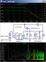
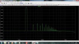
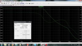
That is what Putzeys says and probably I took it wrongly. In that exsample the amp distortion was never negligible. But in the case of my amp, in my opinion, distortion was negligible without gain redution at low frequences and stayed negligible with the gain reduction. A bonus is better phase behavior, I was afraid a bit of instabillity.
At Loop Gain diagram you can see that there is more then 60dB of negative feedback.
dado
Attachments
Hi all, Dado,
The best way for a beginner like me to tell if an amp gives musical results is building one... For an engineer or technical, the scheme is essential, but I presume not the last word in case of doubt. After building the JLH 80W, whose sound is already very rewarding in the stereo version, I’d like to go further, in a double mono version this time. I don’t intend to build lots of amplifiers because I've no other skills than Ohms law and there are enough to do to improve the whole system before. However I guess this is a good one, doesn’t it ? Let’s go, for it with your help... For me, this is a challenge.
Could you prepare, Dado, one image for a power supply and amplifier PCBs ? I could then eventually try to design a PCB from them. I’ll prepare a list of components for it, but I’m not sure what is the last version.
Thanks !
Nicola
Hi all, Dado,
The best way for a beginner like me to tell if an amp gives musical results is building one... For an engineer or technical, the scheme is essential, but I presume not the last word in case of doubt. After building the JLH 80W, whose sound is already very rewarding in the stereo version, I’d like to go further, in a double mono version this time. I don’t intend to build lots of amplifiers because I've no other skills than Ohms law and there are enough to do to improve the whole system before. However I guess this is a good one, doesn’t it ? Let’s go, for it with your help... For me, this is a challenge.
Could you prepare, Dado, one image for a power supply and amplifier PCBs ? I could then eventually try to design a PCB from them. I’ll prepare a list of components for it, but I’m not sure what is the last version.
Thanks !
Nicola
OK I will check all again as same time passed after I finished my amp. For power supply I will suggest what I used and then you can make dual mono. I'll be back soon.
dado
Hi vac231,
Here are PCB layout and PCB to be used for PCB making. Mirrored one is for the photo way to produce PCB and other one is if you whant to use hot iron and laser printer method.
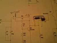
Please check before you start to make PCB and report all errors. Just to remember that on the PCB layout R20 is combination of NFET and resistor, I attached the photo again.
dado
Here are PCB layout and PCB to be used for PCB making. Mirrored one is for the photo way to produce PCB and other one is if you whant to use hot iron and laser printer method.
Please check before you start to make PCB and report all errors. Just to remember that on the PCB layout R20 is combination of NFET and resistor, I attached the photo again.
dado
Attachments
![DADO-T-TMC-2pairs.LAY].jpg](/community/data/attachments/224/224496-fe0c4699ad821a6ec2d94618513753f9.jpg)
![DADO-T-TMC-2pairs.LAY]-only.jpg](/community/data/attachments/224/224538-2cad999b38a1b335bc259e19c78c0940.jpg)
I'm nonplussed. So an article which essentially says "use as much loop gain as you possibly can" is now taken as an excuse to lower loop gain? I mean, yes it can be an easy psychoacoustic fix when you've thrown in the towel as far as loop gain at 20kHz is concerned. But what I'm really trying to say is: work on your circuit to make loop gain at 20kHz higher. Use a T network, for instance. It's the quickest way to boost loop gain on a standard circuit.After readig "The F-word or, why there is no such thing as to much feedback" by Bruno Putzeys http://www.linearaudio.net/userfiles/file/letters/Volume_1_BP.pdf I decided to lower VAS gain, in case if there is enough gain at 20kHz, in my next project too.
@JCX: 100% on the mark with the nonlinear C. There are several "highly regarded" amps out there with constant (or no) loop gain over the audio range where this distortion mechanism dominates starting from a few kHz. Ouch.
Last edited:
"I surmise that, since the amplifier’s distortion was never negligible, making
it constant across the audio band makes it fly under the psychoacoustic radar more easily."
That is what Putzeys says and probably I took it wrongly. In that exsample the amp distortion was never negligible. But in the case of my amp, in my opinion, distortion was negligible without gain redution at low frequences and stayed negligible with the gain reduction. A bonus is better phase behavior, I was afraid a bit of instabillity.
At Loop Gain diagram you can see that there is more then 60dB of negative feedback.
dado
Bruno Putzeys wrote:
" I mean, yes it can be an easy psychoacoustic fix when you've thrown in the towel as far as loop gain at 20kHz is concerned. "
I did not throw in the towel as there is more then 60dB of negative feedback at 20kHz, I was thinking that this is enough for 20Hz as well. In this case the phase behavior is better and I think i could get more stable amp with enough low distortion( in ppm region).
I used T network called here TCM.
I am open on all sugestions and if this use of the TCM will hart this amp i will drop it and use TCM witout VAS(Mr. Putzeys call it Transimpedance stage and that is correct, but VAS is so dipp in the teminology) local negative feedback.
I will appreciate if Mr. Putheys take a look through out this thread and tell me if my diagrams are wrong.
dado
Bruno Putzeys wrote:
" I mean, yes it can be an easy psychoacoustic fix when you've thrown in the towel as far as loop gain at 20kHz is concerned. "
I did not throw in the towel as there is more then 60dB of negative feedback at 20kHz
Oh in that case I wouldn't bother with things like flattening loop gain. I merely noticed that it was perhaps the least "scientific" bit that was lifted from the F article.
Oh in that case I wouldn't bother with things like flattening loop gain. I merely noticed that it was perhaps the least "scientific" bit that was lifted from the F article.
Here on this forum you can find a lot non "scientific" explanation. I took that part from from the F article as here this amp was made before I have found yor article and what you said looked resonable to me. I suppose you meant it for an amplifier whit not so low distortion.
Main reason I used it, was better phase behavior then whitout it. Distortion was quite low already.
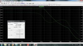
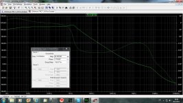
Here are two Loop Gain diagram, one without local VAS FB and one with it.
First one shows phase drop to -174 degree at 20kHz and second one only -154 degree at 80kHz. Phase margin is the same, 65 degree at 2MHz, where the gain drop to zero.
Anyhow I tried both way and I could not hear diference, just I expext the second one could be more stable.
Dado
Attachments
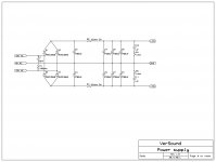
![Powersupply.LAY].jpg](/community/data/attachments/226/226433-4d1a77ba09ed651a6c249491fdcaddf2.jpg)
Hi Dado,
I checked your BOM with my list based on your previous schema. That’s OK for almost all components (I saw some changes in capacitor and resistor values).
I’ve some questions :
a) In your previous schema, Q11 was BC556B and Q12 BC546B. In your last schema, values are inverted. What is correct ?
b) D01 and D02 are MUR460 in your previous schema. I found ON SEMICONDUCTOR MUR460G. Are other types possible ?
c) Reference for L1 (2uH) ?
d) Q1, Q2, Q3 (2SA970). I found Toshiba 2SA 970BL. OK ?
e) Q5, Q6, Q7 (2SC2240). I found Toshiba 2SC 2240BL. OK ?
f) Q8, Q96 (NJW4281). I found ON SEMICONDUCTOR NJW0281G. OK ?
g) Q10, Q97 (NJW4302). found ON SEMICONDUCTOR NJW0302G. OK ?
h) Q9. I found Fairchild 2SC3503 STU Series with various hFE. Which hFE to choose (40, 60, 100 or 160 ) ?
i) R83 (1K). Is multiturn trimmer and which power handling ?
j) I found that electrolytics C5, C7 and C10 were normal ESR and other C6, C12, C16 and C17 were low ESR. Is that correct ?
k) Can I replace fuses with a special card for DC detection at speaker output, or are this two types of protection complementary ?
l) Are all resistors 0.25W (but R99 3W) ?
Could explain what is the topology difference with JLH 80W amp in simple words ?
Nicola
Hi Nikola,
Here it is:
a) In your previous schema, Q11 was BC556B and Q12 BC546B. In your last schema, values are inverted. What is correct ?
Q11 - BC546B and Q12 - BC556B I did a new drawing with expresSCH software and made a mistake
b) D01 and D02 are MUR460 in your previous schema. I found ON SEMICONDUCTOR MUR460G. Are other types possible ?
Any diode 300-600V and 3A or more.
c) Reference for L1 (2uH) ?
I used 1.2mm diametar enameled wire and coild it on 7mm dia pencil cca 20 coils.
d) Q1, Q2, Q3 (2SA970). I found Toshiba 2SA 970BL. OK ?
OK
e) Q5, Q6, Q7 (2SC2240). I found Toshiba 2SC 2240BL. OK ?
OK
f) Q8, Q96 (NJW4281). I found ON SEMICONDUCTOR NJW0281G. OK ?
OK
g) Q10, Q97 (NJW4302). found ON SEMICONDUCTOR NJW0302G. OK ?
OK
h) Q9. I found Fairchild 2SC3503 STU Series with various hFE. Which hFE to choose (40, 60, 100 or 160 ) ?
I used series E 100-200, F is good to 160-320
i) R83 (1K). Is multiturn trimmer and which power handling ?
Look PCB, it vertical type normal one(very low power handling)
j) I found that electrolytics C5, C7 and C10 were normal ESR and other C6, C12, C16 and C17 were low ESR. Is that correct ?
Only C5 is not important, all others better to have low ESR. C10 is not elko (0.22uF)
k) Can I replace fuses with a special card for DC detection at speaker output, or are this two types of protection complementary ?
I never use a relay in the audio chain. Off course you can use special card, but if it uses a relay to switch of the loudspeaker
conntact will deteriorate durin the time and I don't like that. You can live fuses it will not have any influence.
l) Are all resistors 0.25W (but R99 3W) ?
R98 should be 2W and R99 3W, all others 0.25W is OK.
Regarding JLH 80W amp, it uses lateral output FETs and uses quite low negative feed back, cca 20dB at 20kHz.
My modification of JLH uses cca 40dB of NFB at 20kHz.
I am still listening this amp, and it is very stable, not so before mdification.
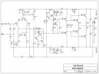
This amp here is classic one with all bipolar transistors, but with very high negative feedback cca 60dB at 20kHz. It is possible to have it so high because it uses different compensatio not standard Miller compensation, so called TMC. If you like to know more about it search this forum, there it was a lot discution about it.
Dado
Here it is:
a) In your previous schema, Q11 was BC556B and Q12 BC546B. In your last schema, values are inverted. What is correct ?
Q11 - BC546B and Q12 - BC556B I did a new drawing with expresSCH software and made a mistake
b) D01 and D02 are MUR460 in your previous schema. I found ON SEMICONDUCTOR MUR460G. Are other types possible ?
Any diode 300-600V and 3A or more.
c) Reference for L1 (2uH) ?
I used 1.2mm diametar enameled wire and coild it on 7mm dia pencil cca 20 coils.
d) Q1, Q2, Q3 (2SA970). I found Toshiba 2SA 970BL. OK ?
OK
e) Q5, Q6, Q7 (2SC2240). I found Toshiba 2SC 2240BL. OK ?
OK
f) Q8, Q96 (NJW4281). I found ON SEMICONDUCTOR NJW0281G. OK ?
OK
g) Q10, Q97 (NJW4302). found ON SEMICONDUCTOR NJW0302G. OK ?
OK
h) Q9. I found Fairchild 2SC3503 STU Series with various hFE. Which hFE to choose (40, 60, 100 or 160 ) ?
I used series E 100-200, F is good to 160-320
i) R83 (1K). Is multiturn trimmer and which power handling ?
Look PCB, it vertical type normal one(very low power handling)
j) I found that electrolytics C5, C7 and C10 were normal ESR and other C6, C12, C16 and C17 were low ESR. Is that correct ?
Only C5 is not important, all others better to have low ESR. C10 is not elko (0.22uF)
k) Can I replace fuses with a special card for DC detection at speaker output, or are this two types of protection complementary ?
I never use a relay in the audio chain. Off course you can use special card, but if it uses a relay to switch of the loudspeaker
conntact will deteriorate durin the time and I don't like that. You can live fuses it will not have any influence.
l) Are all resistors 0.25W (but R99 3W) ?
R98 should be 2W and R99 3W, all others 0.25W is OK.
Regarding JLH 80W amp, it uses lateral output FETs and uses quite low negative feed back, cca 20dB at 20kHz.
My modification of JLH uses cca 40dB of NFB at 20kHz.
I am still listening this amp, and it is very stable, not so before mdification.
This amp here is classic one with all bipolar transistors, but with very high negative feedback cca 60dB at 20kHz. It is possible to have it so high because it uses different compensatio not standard Miller compensation, so called TMC. If you like to know more about it search this forum, there it was a lot discution about it.
Dado
C3 could be 10V and if you can find with so low voltage you can increase the value even up to 1000uF. D. Self recomandet here high value but best quality you can find, Elna silmic or better.
C5 could be less then 50V but not less then 30V if there is a one with that voltage.
C7 better to be 63V.
all others 50V is good enough.
C5 could be less then 50V but not less then 30V if there is a one with that voltage.
C7 better to be 63V.
all others 50V is good enough.
Hi Dado,
A. About other capacitors not electrolytics. Is the quality not significative for some of them (like the green C4) for example ?
B. I see the central thermal aluminium you use to cold Q94 and Q95 :
B1. Is this main dissipator DIY or available somewhere ?
B2. You have added an additional piece of metal to it.. Are Q94 and Q95 so hot ?
Have a nice day!
Nicola
- Home
- Amplifiers
- Solid State
- bootstrapsCCS+T-TMC