If you use OP27 (chipper then NE5534)...
I meant costlier then NE5534...
Hi Luke,
I'm talking about error opamp in W. Jung's regulators, not the servo opamps at Dynahi headamp. Anyway, for servo opamp duties, OPA227 is not optimal, 'cos it's BJT input opamp and you want low input bias current wich any (almost) BJT input opamp doesn't have...so just use (good for application) J-fet input opamp like LF411, AD711 etc.
I'm talking about error opamp in W. Jung's regulators, not the servo opamps at Dynahi headamp. Anyway, for servo opamp duties, OPA227 is not optimal, 'cos it's BJT input opamp and you want low input bias current wich any (almost) BJT input opamp doesn't have...so just use (good for application) J-fet input opamp like LF411, AD711 etc.
I'll change R20/R21into two seperate resistors, and connect the capacitors properly, do i omit C1 and C12?
Nope.
What's terminal 5 and 11?
Look at the W. J. pdf article, they are the positive and negative raw supply terminals.
For servo, I'm using OPA134PA which AMB recommends.
Ok, for opamp vs. opamp, in light to some recent searching...
Turns out the NE5534's maximum supply rail is 20volts, which unloaded my unregulated voltage will be sitting at 25+volts.
Or did i just forget about the power of the 22ohm resistor between the op amp and the supply rails?
I've attached the updated board layout for the regulator
What does the voltage forward need to be for the red LED's? >1.6volts?
Attachments
I must have ended up on the wrong datasheet! Doh
Yes, NE5534a is a excellent choice, now compensation...
You said pins 5+8, just like the application drawing in this data sheet on page two?
http://focus.ti.com/lit/ds/symlink/ne5534a.pdf
Luckily enough, I think i have some 22pF 50volt caps. I need to organize my parts mess, but just keeps piling up!
Now on the topic of LED's, what is the significance of the voltage forward? I've got 1.65volt and 1.85volt red LED's, I'll order a bunch of 1.6volts, which of these would be adequate for the super regulator?
Based on the values for R3 and R5, vout should be +/-15.35volts, cool! I might just spend the time to match the resistors to see how close i can get to the target vout.
All for sport!
I must have ended up on the wrong datasheet! Doh
Yes, NE5534a is a excellent choice, now compensation...
You said pins 5+8, just like the application drawing in this data sheet on page two?
http://focus.ti.com/lit/ds/symlink/ne5534a.pdf
Luckily enough, I think i have some 22pF 50volt caps. I need to organize my parts mess, but just keeps piling up!
Yes, just place compensation cap beetwen pins 5 and 8 (it should be polystyrene or silver mica, but for now plane ceramic will do)
Now on the topic of LED's, what is the significance of the voltage forward? I've got 1.65volt and 1.85volt red LED's, I'll order a bunch of 1.6volts, which of these would be adequate for the super regulator?
Any LED will do, but you should use preferable red ones with no less then Vf (forward voltage drop) ~1V65. Vf will define current in conjunction with value of the resistor on the base of the transistor. Math....(Vf - Vbe)/R=I....(1V65-0,65)/249R=4mA for example (Vbe= voltage between transistor's base and emitter).
Based on the values for R3 and R5, vout should be +/-15.35volts, cool! I might just spend the time to match the resistors to see how close i can get to the target vout.
As I said before, use 1k1/910R combo and everything will be fine.
Last edited:
Hi Knightofawesome,
have you got a schematic for that board, I may make one as well as I intend on building this HP Amp.
Have you thought of getting the whole psu on one board, ie rectifiers, filter caps etc?
Yep
http://waltjung.org/PDFs/Regs_for_High_Perf_Audio_3.pdf
There is only one thing that I want you to change in W. Jung regs... split resistors R20/R21 in half, say 5k9 + 5k9, at the resistors junction point connect one end of electrolitic cap of 100uF/25V, the other end goes to raw DC input (terminal 5 for positive and terminal 11 for negative reg., be cerefull about orientation of the new added caps!!!)
I found whatever I attempted to make the entire PSU on one board, I ended up making a 20cm long train instead. I think breaking this apart and making it more modular is the better way to go. Should allow for isolating the transformer from the sensitive parts.
Also note that i'm attempting to generate some interest over at head-fi for a possible GB for these super regulators boards, I'll see how that goes. although the boards will need to be much nicer then they are now.
There is only one thing that I want you to change in W. Jung regs...
Well, I have another "to do thing" about W. Jung MkI regs...
1. Move R6/R18 to the emmiter side of transistors Q1/Q2 respectively (now the opamp have it's power from regulator output, not from raw supply
2. Exchange D8/D10 1N4148 for 1N5235B 6V8 zener diodes and for R19/R22 use 249R resistor instead 100R ones. Watch orientation of zeners, it's reverse of small signal diode like an 1N4148. Now, output from error opamp sits at ~1/2 of regulators output voltage which will make life easier for poor opamp.
All this mods are implemented in improved W. Jung regulators.
")
Then it's very a good idea to incorporate these changes, I'll leave out C2/C3 and C5/C13 too. I believe i can organize this much better.
Should i use green LED's with this now? in the parts list, it says to use a green LED with 2.2volts forward
Should i use green LED's with this now? in the parts list, it says to use a green LED with 2.2volts forward
Attachments
Last edited:
I would design a place in pcb board for C2/C3, in some cases, some types of opamps needs them to be stable...NE5534 would not need them, but in case you change for some wired, high-speed opamp, they could be a life saver. So, design them in pcb, but you don't have to install.
Yep
http://waltjung.org/PDFs/Regs_for_High_Perf_Audio_3.pdf
I found whatever I attempted to make the entire PSU on one board, I ended up making a 20cm long train instead. I think breaking this apart and making it more modular is the better way to go. Should allow for isolating the transformer from the sensitive parts.
Also note that i'm attempting to generate some interest over at head-fi for a possible GB for these super regulators boards, I'll see how that goes. although the boards will need to be much nicer then they are now.
Im up for a couple of boards.
I would design a place in pcb board for C2/C3, in some cases, some types of opamps needs them to be stable...NE5534 would not need them, but in case you change for some wired, high-speed opamp, they could be a life saver. So, design them in pcb, but you don't have to install.
I'll really need to split this board layout now... I'll leave the single sided PCB as is
I'll turn it into a 2 layor PCB and add the two(four) components in.
I've attached the (hopefully) final singlesided PCB, I'll work on the double sided later
Attachments
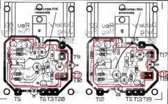
I started the double sided PCB, under the red top layer is the PCB in the previous post, what do you think?
I'm considering buying the K2SA/K2SC alternatives rather then the out of production Toshiba's.
I'm finding it hard to get into the dynalo again, It's been sitting on my computer for a couple of days now untouched, I'm getting tempted by other projects online, but i must resist!
Cheers
I'm considering buying the K2SA/K2SC alternatives rather then the out of production Toshiba's.
I'm finding it hard to get into the dynalo again, It's been sitting on my computer for a couple of days now untouched, I'm getting tempted by other projects online, but i must resist!
Cheers
Attachments
I started the double sided PCB, under the red top layer is the PCB in the previous post, what do you think?
A proper way to ad a ground plane to W. Jung SupeRegulators...Also ground plane should be connected only to terminal T7/T15 (marked as red X)
Attachments
Last edited:
This should be correct now, I had to create a separate network to attach the one pin to the shield, this should be better now. I'll add the optional compensation for the OP amp tomorrow. Hopefully I can generate enough interest for something to happen.
Attachments
- Status
- This old topic is closed. If you want to reopen this topic, contact a moderator using the "Report Post" button.
- Home
- Amplifiers
- Solid State
- Gilmore Dynalo troubleshooting