I'll concentrate building a schematic for the PSU tomorrow, Should i add anything after the LM3x7 regulators to improve regulation? It's hard to find any circuits that provide measurements.
I'll make a PCB layout of a filter before the transformer with a 1Meg resistor, a 0.22uF cap, and a 1.9mH 4amp Common Mode Choke. I believe this will add stability and noise reduction, possibly eliminate the problem of my computers PSU.
Since you are able to each your own boards, there is nothing to stop you produce positive and negative Walt Jung's regulators. For board layout, thematics and everything else you want to know about it is at W. Jung site Home
Everything you need to know about series, low drop, low impedance, low noise regulators.
http://waltjung.org/PDFs/Regs_for_High_Perf_Audio_1.pdf
http://waltjung.org/PDFs/Regs_for_High_Perf_Audio_2_A.pdf
http://waltjung.org/PDFs/Regs_for_High_Perf_Audio_2_B.pdf
http://waltjung.org/PDFs/Regs_for_High_Perf_Audio_2_C.pdf
http://waltjung.org/PDFs/Regs_for_High_Perf_Audio_3.pdf -> here are schematics, board layouts and wiring to build your own regulators.
Improved versions are also available (with LM317/337 preregulators) http://waltjung.org/PDFs/Improved_PN_Regs.pdf ,but my best advice is to stick with the basic version, since boards layout is already given and plays a major role in regulators performance.
As for rectification and filtering use BYV27 to build diode bridges, folowed by >33mH/min. 1A common mode choke (or 1-2R2/0,5W resistor), 220nF+2uF+2200uF, 4R7-6R8/0,5W resistor, 2200uF+2uF+220nF (lineup from left to right)
Do you want the transformers secondary wiring to run in parallel or series? I'd like to keep some similarity to the twisted pear PSU, using most of the parts i already have.
What's so special about the BYV27 vishay diodes? Is it the uberfast recovery time?
I can't help but feel that the PSU ripple filtering will be a little excessive, I have no problem with the RCRC filter, but most of the ripple (if not all) will be filtered out by the regulation. If i install the common mode choke after the rectifiers, do i need that conditioning circuit before the transformer i mentioned? If I'm running the transformer in parallel, I think it would be more cost effective to have it before the transformer.
Can the 2uF cap be a electrolytic? Is this cap necessary, I don't see the advantage that this brings due to the cost that this will be. I want to keep this as cost effective as possible.
I can't help but feel I'm going overboard here on getting perfect regulation, is it really that necessary? I only wanted a rock solid regulation because i noticed the voltage rails were in sync with the offset. I just wanted a simple improvement of the LM317/LM337.
Edit: will this LED work?
http://search.digikey.com/scripts/DkSearch/dksus.dll?Detail&name=516-1323-ND
I can't remember which one i ordered, but i thought it was a 1.6volt LED and it looked just like that one
Last edited:
The best way is to have 2 transformers, each for only one channel, with split secondaries, so 4 wires on transformer secondary side, no center tap. Each transformer secondary side follow 2 diode bridges. After diode bridges comes CM choke or 4 1-2R2 resistors, then first capacitor bank, then 4R7-6R8 resistors followed by 2nd capacitor bank. That way you have almost ripple free voltage output prior to regulators, and they will thank you for you effort.
Why would you need filtering on primary side of transformer?
BYV27 is chip, fast, but also soft recovery which is a property you haven't notice.
Yes, you can put good quality 2u2 electrolytic instead film capacitor.
The point of such elaborated PSU is the fact that entire PSU is in series to load, so effectively you are listening an amp and it's PSU, especially the last capacitor in PSU.
LM317/337 have to much noise, the output impedance go sky-high with freq. and are very slow...you amp is way faster then they are.
For inspiration see this http://www.diyaudio.com/forums/solid-state/139239-best-low-noise-regulator.html#post1755672
Last edited:
I doubt you'd have any of those boards hanging around, they would be damn nice to work with. I'm a afraid I'd tear off the vias on the waltjung regulator PCB, much like i did many times on the Dynalo board. I've also got a nice offboard heatsink just waiting to be used, and segregating the PSU into something like a transformer board, a smoothing board, and then a regulator board would be helpfull.
The filtering on the primary side of the transformer was not a filter, It was a RF filter, That way if i head one on the primary side, I wouldn't need two on the secondary side.
Speaking of Dynalo board, The board at AMB is $12 US... Thats fine, and acceptable, I have no problem with that.
Just turns out that shipping is roughly $12.20 which is quite far off from okay, I'll ask djgardner if he has any boards lying around that he wouldn't mind selling.
Excellent, I shall use a 2uF electrolytic.
Thanks!
Sorry, all my W. Jung SupeRegulator are given to fellow diy co. in Croatia, but if I have the knowledge to etch my own board like you, I wouldn't wait a second to build regulators as described in pdf article few post above...Don't think... build!
As for RF filter, you can buy readily built ones for not much $.
I paid about 185$ for 2 x Dynahi board + 2 x PSU board professionally made here, but I insisted on few extras.
As for RF filter, you can buy readily built ones for not much $.
I paid about 185$ for 2 x Dynahi board + 2 x PSU board professionally made here, but I insisted on few extras.
Yep you found my problem, I think to much!
I'll copy the schematic into eagle, I need to change the size of the vias or this will all end in tears. Unless you've got the eagle schematic available (board layout if possible)?
I'll still use multiple boards, Transformer board (I'll use it from my previous PSU board), rectifying and smoothing board, and super regulator board. The regulator board will be closest to Dynalo board. The only thing I haven't worked out is the grounding scheme... Hmmm
Star point should be on the rectifying and smoothing board, I think...
Ohwell, work the rest out tomorrow.
Why would your Eagle boards end in tears...if it works for everyone else it will work for you to. Just copy layout, don't change a bit and everything will bi ok.
As for my Eagle files, they are all gone for good along with hard drive of my old PC, sorry.
Ground scheme you say...will come to that, but as I already said, thing will be much simpler, but costlier, if you use 1 transformers for each channel with split secondaries and 2 diodes bridges for each channel.
I was talking about the board layout from the PDF file, the vias are too small.Why would your Eagle boards end in tears...
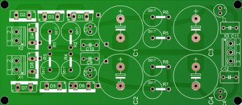
I've attached the board layout for the filter and rectifier, Jumpers are not show but should be self explanatory. The wires will just be soldered onto the traces, not going on top of the board. I paralleled the resistors, the first stage resistors are 2r2 and the second stage is 10ohm.
I'll try laying out the super regulator boards tomorrow.
I haven't ordered any parts yet, might order the transistors tonight if i have anymore time.
What about gain? I found 5x and 3x to be too low, I had to turn the pot quite for to get volume out of it, should i just build with the default 11x?
Attachments
Last edited:
OK, working on the regulators now
I don't quite see how to find the output voltage, I know the voltage divider sets the gain, but i don't quite see what sets the drops in the voltage, is it a default 2volts?
Can X1/X2 be substituted with any high performance single rail OP amp? The default op amps are stretching my budget. (such as OP27?)
(still haven't order anything)
Take your time, I'm in no rush
I don't quite see how to find the output voltage, I know the voltage divider sets the gain, but i don't quite see what sets the drops in the voltage, is it a default 2volts?
Can X1/X2 be substituted with any high performance single rail OP amp? The default op amps are stretching my budget. (such as OP27?)
(still haven't order anything)
My source is a Gamma1 DAC, I'm using a 50K pot, maybe that's why it was so quietI have to go sleep 'cos I'm working early tomorrow, so will deal with your board latter (tomorrow night probably).
About gain, what is your source output...gain of 5 is usually more then adequate for headamp/headphones.
Take your time, I'm in no rush
Last edited:
LM329DZ is voltage reference (6V95) for the error opamp and it will multipy this voltage by defoult gain of 2x (but it can be change of course, we will come to that latter), so your output voltage will be 13V9 with gain setting resistors of 1k/1k.
Error opamps should be unity gain stable, low noise, and fast...so the chipest option would be venerable Philips NE5534D, but with edded compensation of 22-25pF at pins 5 and 8 to make it stable at unity gain.
Error opamps should be unity gain stable, low noise, and fast...so the chipest option would be venerable Philips NE5534D, but with edded compensation of 22-25pF at pins 5 and 8 to make it stable at unity gain.
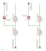
There is only one thing that I want you to change in W. Jung regs... split resistors R20/R21 in half, say 5k9 + 5k9, at the resistors junction point connect one end of electrolitic cap of 100uF/25V, the other end goes to raw DC input (terminal 5 for positive and terminal 11 for negative reg., be cerefull about orientation of the new added caps!!!)
What about gain? I found 5x and 3x to be too low, I had to turn the pot quite for to get volume out of it, should i just build with the default 11x?
Yes, you should set the gain to default 11x 'cos the entire headamp is design and compensated for default gain (I hope).
This is the current transformer I'm using
Digi-Key - TE2253-ND (Manufacturer - L01-6353)
Since I only have laminated core transformers, other then the PCB mount
(It says 1A dual @15volts, but the transformer i have here says 0.63Amp)
Also, since the proboard for the Dynalo has the power rails are connected to powerplanes throughout the board, using more then four regulators would be pointless.
Would a NE5534D be better then a OP27 in this application?
That explanation of how to calculate the vout makes a lot of sense, so to get ~15.5volts out, I'd need a 1k2 resistor in R5/R16's spot
I'll change R20/R21into two seperate resistors, and connect the capacitors properly, do i omit C1 and C12?
What's terminal 5 and 11?
Attachments
The output voltage is calculated from the following formula:
Vout = Vref * (1+R5/R3).
Additionally R5 // R3 (the impedance of the two resistors in parallel) should equal 500 Ohms.
To make this easier the following formula could be applied:
R3 = (500 * Vout) / (Vout – Vref)
Once the above is calculated, apply the value obtained above to the following formula:
R5 = R3 * ((Vout – Vref) / Vref)
The two values then can be selected from the closest standard value, or made up from parallel / series combinations.
Ok, based on the measurements I just took of the loaded PSU was ~24.3volts on both rails (+/-). That with a voltage drop across the output resistors was ~0.25volts, quite underbiased. I also faintly remember when the voltage drop across the output resistors was 0.95 the unregulated voltage was something like 17.5volts. Meaning that if I set the bias to the output transistors to have 0.35volts across the output resistors (later on the new board), It should be above 18.0volts... which would be a assumption (bad bad). So ideally because I'm only driving grado headphones, I should set the output voltage to 15volts.
Vout=15.0volts
The voltage referance of LM329DZ is 6.95
Vref=6.95
Put this into:
R5 = R3 * ((Vout – Vref) / Vref)
and end up with:
R5=R3*1.16
Which will go into the equation of:
((R3*1.16)*R3)/((R3*1.16)+R3)=500
R3 solves for 931.677, going back to the previous equation:
(R5*931)/(R5+931)=500
says that R5 is 1079.13
Excellent, Does a 15volt supply rail sound good? Should i attempt 16volts?
What about using a OP27 for X1/X2?
Cheers!
So ideally because I'm only driving grado headphones, I should set the output voltage to 15volts.
Correct.
Vout=15.0volts
The voltage reference of LM329DZ is 6.95
Vref=6.95
Put this into:
R5 = R3 * ((Vout – Vref) / Vref)
and end up with:
R5=R3*1.16
Which will go into the equation of:
((R3*1.16)*R3)/((R3*1.16)+R3)=500
R3 solves for 931.677, going back to the previous equation:
(R5*931)/(R5+931)=500
says that R5 is 1079.13
Your math is good, so I'll give you A+
") ...Just use the closest value you can get for R3(R17) and R5(R16), say 1k1/910R combo.
...Just use the closest value you can get for R3(R17) and R5(R16), say 1k1/910R combo.Does a 15volt supply rail sound good? Should i attempt 16volts?
It doesn't matter much, just pick the best matching resistors for equation given above.
If you use OP27 (chipper then NE5534) you can use it without compensation cap, because it's unity gain stable, but it's slower opamp then NE5534...I would go for Philips (Signetics) NE5534, or maybe Fairchild which is I presume, exact copy of the original Signetics NE5534 opamp.What about using a OP27 for X1/X2?
- Status
- This old topic is closed. If you want to reopen this topic, contact a moderator using the "Report Post" button.
- Home
- Amplifiers
- Solid State
- Gilmore Dynalo troubleshooting