I wanted to share what I've been working on for the past year or so. I been following the "The very best amplifier I've ever heard" (TVBAIEH) thread and it got me thinking. The best amp I've heard is the Allison variant that several folks hear helped with. When I say helped with, they came up with the scheme, I built and tested it. I want to acknowledge Keantoken, PaulBysouth and KenPeter who all helped immeasurably. You can read about the development of this amp on the following: (this configuration starts at post #308) http://www.diyaudio.com/forums/solid-state/139564-simulation-analysis-several-unique-allison-based-output-stages.html
I've compared this amp against a triple emitter follower and a nice 50watt Rotel amp. I can't claim to have heard all the world's great amps, but, this one is just a bit smoother than the others. I really enjoy music that features the human voice, from opera, to Frank Sinatra and everything in between. This amp helps those voices shine! I know these opinions are subjective, so, that's what you get...
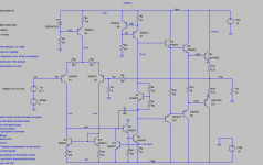
To test the amp in simulation; I've compared it to Bob Cordell's Triple emitter follower Figure 3.10 on page 65 of his book. Using Bob's model files and Thd setup, I've put together the Figure 3.10 as a baseline and used the front end of this amp to graft the modified Allison on as the CAS.
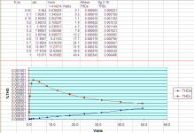
I then ran each in simulation at various input voltages to get a picture of THD.
A note on the modified Allison, it runs in class A up to about 16watts into 8 ohms in this configuration, but, it can be easily adjusted by changing out one resistor.
Got to go, a bit more later.
I've compared this amp against a triple emitter follower and a nice 50watt Rotel amp. I can't claim to have heard all the world's great amps, but, this one is just a bit smoother than the others. I really enjoy music that features the human voice, from opera, to Frank Sinatra and everything in between. This amp helps those voices shine! I know these opinions are subjective, so, that's what you get...
To test the amp in simulation; I've compared it to Bob Cordell's Triple emitter follower Figure 3.10 on page 65 of his book. Using Bob's model files and Thd setup, I've put together the Figure 3.10 as a baseline and used the front end of this amp to graft the modified Allison on as the CAS.
I then ran each in simulation at various input voltages to get a picture of THD.
A note on the modified Allison, it runs in class A up to about 16watts into 8 ohms in this configuration, but, it can be easily adjusted by changing out one resistor.
Got to go, a bit more later.
Attachments
Can you run other simulations?
I'd like to see HD2 to 9 at 10khz, 20khz and 50khz (at just 1W would be fine).
Besides, I'm more interested in your listening opinions than the sims. Which which amplifiers (or better, output stages connected to the same frontend) did you compare it?
I'd like to see HD2 to 9 at 10khz, 20khz and 50khz (at just 1W would be fine).
Besides, I'm more interested in your listening opinions than the sims. Which which amplifiers (or better, output stages connected to the same frontend) did you compare it?
Can you run other simulations?
I'd like to see HD2 to 9 at 10khz, 20khz and 50khz (at just 1W would be fine).
Besides, I'm more interested in your listening opinions than the sims. Which which amplifiers (or better, output stages connected to the same frontend) did you compare it?
Yes, I'll run more simulations.
I have been using an LME49811 for the front end on all my test amps. It's on a separate board that plugs into the CAS board, so that I can swap out different typologies easily. In all I have built 7 or 8 different CAS typologies - some minor variations on others. I compared it to a pure Class A Allison, a double emitter follower and a triple emitter follower. The guys from National say that the 49811 contains pre-drivers, so that a triple isn't required, but, who knows? In comparison to the double emitter follower with the same type of driver and output transistors, re resistors, etc. the modified Allison made the voices more natural, more open and less strident. It's tough to describe these things, the double emitter follower sounded great, the modified Allison just sounded better in comparison over many hours of listening.
Ken
Oh, so you are the guy that Anthony talked me about. Yup that would be me, hopefully he said nice things.Same output transistors? Same type onsemi 3281/1302's, thermal trak version for the double emitter follower configuration.Now much NFB?
I meant how much NFB? Same in both cases?
As far as I know, though I believe that Keantoken mentioned that the Allison has a kind of local NFB loop. But the NFB is set up like the simulation. The gain setting resistors for both configuration.
hd2-9
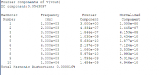
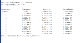
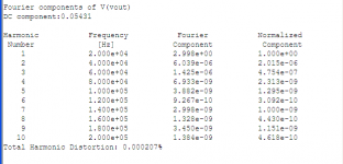
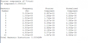
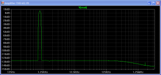
The following are the HD2-10 results at 1k, 10k, 20k and 50k respectively and the FFT at 1k. All at approx. 1 watt output.
The following are the HD2-10 results at 1k, 10k, 20k and 50k respectively and the FFT at 1k. All at approx. 1 watt output.
Attachments
Klewis,
Referring to the second schematic in post #1 (ie the Allison circuit), if you add a resistor (of about 100 ohms) between the emitters of Q11 and Q18, then these output transistors will never turn off and the only switching in the circuit will be the two Schottky diodes. I doubt that you'll be able to measure any difference though.
Some other things you might like to try:
- Use irf610 and irf9610 Mosfets for the drivers (in place of Q3, Q6), or
- swap the output transistors (Q11 and Q18) for some big mosfets (irf240 and irf9240 or similar).
Don't forget the gate stopper resistors.
Paul Bysouth
Klewis,
Referring to the second schematic in post #1 (ie the Allison circuit), if you add a resistor (of about 100 ohms) between the emitters of Q11 and Q18, then these output transistors will never turn off and the only switching in the circuit will be the two Schottky diodes. I doubt that you'll be able to measure any difference though.
Some other things you might like to try:
- Use irf610 and irf9610 Mosfets for the drivers (in place of Q3, Q6), or
- swap the output transistors (Q11 and Q18) for some big mosfets (irf240 and irf9240 or similar).
Don't forget the gate stopper resistors.
Paul Bysouth
Hi Paul,
Nice to hear from you again. Your help in the past has been great! I think you meant Q17 & Q18, I'll give this a try. The resistors that feed the emitters of these transistor are different values. I found that if you tune these so that the collector currents are equal, it drives the distortion down further. My implementation plan includes a pot at one of these resistors to balance the current, ultimately replaced by a fixed resistor.
I've actually been using mje15034/35's for the drivers, they are much more stable than the 2sc4793/a1837 used in the simulation. They also have a close match pnp to npn (keantoken's suggestion). What do you see as the are the benefits of the mosfets for drivers and outputs?
Ken
Klewis,
Referring to the second schematic in post #1 (ie the Allison circuit), if you add a resistor (of about 100 ohms) between the emitters of Q11 and Q18, then these output transistors will never turn off and the only switching in the circuit will be the two Schottky diodes. I doubt that you'll be able to measure any difference though.
Paul Bysouth
Paul,
Maybe I got this wrong, Q17/Q18 are the small current transistors just to the left of the Allison pair and Q11/Q16 are the output transistors, which did you mean?
Ken
Ken,
re Post #11, I meant the output transistors Q11 and Q16 (the values are hard to read off the image in post #1). A resistor between their emitters will force them to stay on, irrespective of what the Schottky diodes are doing.
The small drivers could be replaced by small Mosfet drivers (I'm using irf610 & irf9610), which can supply large amounts of base current to the output stage without loading the VAS stage.
You should also have a look at Nelson Pass's patent 4752745 of June 1988, which uses an OptoCoupler to control the bias. Similar to Allison's scheme, but simpler.
Paul Bysouth
The small drivers could be replaced by small Mosfet drivers (I'm using irf610 & irf9610), which can supply large amounts of base current to the output stage without loading the VAS stage.
I think this circuit needs a closed matched P and N drivers, and that will NEVER happen with IRF mosfets, since their P process is flawed.
The following are the HD2-10 results at 1k, 10k, 20k and 50k respectively and the FFT at 1k. All at approx. 1 watt output.
TYVM
This explain why it sounds better (assumuing 10times worse real world results)
")
Lower distortion NOT accompanied by more high order artifacts make the sound cleaner. There is of course a limit, under which pursuing for PPM thd is pointless, but I dont really know where that limit lies.
Hi Ken,
How a temperature compensation is working, what transistors are fixed together on a heatsink?
dado
Hi dado,
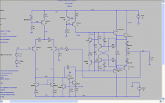
I've posted an enlarged schematic of the output section so that it is easier to see componet numbers and values. (I use a small table pc, so the screen captures aren't so great) Bias is set by R14, I basically try different size resistors at this location until the temperature of the heat sink gets hot, but, not too hot
 The higher the value of R14 the higher the bias. I typically start at 90 ohms and step up in 10 ohm increments. In this way you can tune the amp to the size heat sink available.
 Only the output transistors are mounted on the heatsinks. Diode D2 is thermally bonded to Q17 and kept away from the heatsink, the same for D3 and Q18.
I've never experienced thermal runaway on this amp, though once I over biased it and cooked the output transistors - no smoke, it kept running, but the tone changed. My singers sounded quite different...
Ken
TYVM
This explain why it sounds better (assumuing 10times worse real world results)
Lower distortion NOT accompanied by more high order artifacts make the sound cleaner. There is of course a limit, under which pursuing for PPM thd is pointless, but I dont really know where that limit lies.
I've spotted an error in the bias settings that don't affect the values at 1 watt, but, will most likely affect the values above 15 or 16 watts. I had forgotten to adjust the current that feeds the output down to 6.8ma (what the LME49811 makes) and therefore had it running class A all the way up to 50 watts. I'll re-run and repost later today.
Ken
- Status
- This old topic is closed. If you want to reopen this topic, contact a moderator using the "Report Post" button.
- Home
- Amplifiers
- Solid State
- A different CAS typology with very low THD