What's with the capitals? You do this in many of your posts !
I prefer to use low value resistors in series rather then high value resistors in parallel.
1.) it ensures that each resistor sees a maximum voltage that is a fraction of the mains voltage, whereas the parallel see the full mains voltage ~ 360Vpk + spiking transients.
2.) the wire inside a low value resistor will be considerably shorter and thicker than the wire in an equal power higher value resistor. That thicker wire will be more tolerant of overload current.
Good separation of Mains from LV side.
Don't like the RC timer. Time varies with mains voltage.
Don't like the lack of current going to the transistor switch. The relay may not pull in and the transistor may overheat.
Whoever designed this forgot about the practicalities of transistor switching and reliability.
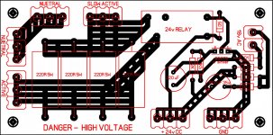
Yes, you need to supply 24V DC or 18V AC power for this circuit to work. Either one is OK but you need these to power the 24V relay. Also, the GND connections at the bottom right corner must be connected to a ground point for the relay to trigger.
The incoming AC power is connected to the Active and Neutral connections on the end of the board. Your power amp is connected to the "Slow Active" and Neutral connections on the side of the board. Notice that there are several resistors between the Active and "Slow Active" connections. When the AC power is started to the board, the resistors restrict the current flow. After a very short time (for instance 100milli seconds or less) the relay should cause the connection between the Active and "Slow Active" areas to be connected with a short, which bypasses the resistors.
Andrew has already brought up a few potential problems with the circuit so I will defer to him. The following are some general comments on the board:
Since the connection for the relay is made only via the traces on the circuit board, they must carry all the current for the amplifier. You should make sure that the trace width and thickness is sufficiently large to not overheat, etc. Also, make sure that the relay is rated for your AC voltage and current demand of your amplifier. You might also want to connect the same wire to all three terminals of the Active, Neutral, and "Slow Active" terminal blocks to share the current flowing through each one.
-Charlie
Also, the GND connections at the bottom right corner must be connected to a ground point for the relay to trigger.
That is what the transistor does - closes the circuit to ground after a short delay.
Could be better. I don't like resistors - thermistors are much better and safer. I don't agree with Andrew on the RC timer - it is not greatly affected by supply fluctuation.
If a thermistor is used, a much longer time period can be used before the relay closes.
There's nothing wrong at all with using resistors in this way. The magnetic field in the transformer will begin to stabilize after a few tens of milliseconds and by 200mS the regulator caps have partially charged and current demand will drop to normal levels. So you only need to limit current inflow (via the power resistors) for a fraction of a second.
Rod Elliot has some good advice regarding/against thermistors at these links:
Soft-Start Circuit For Power Amps
Inrush Current
-Charlie
The relay that would fit that footprint would be a typical OMRON type G2R-1 24V with an operating current of 21 mA, This is a Darlington pair with gain >750, base current of 1 mA would be more than sufficient to drive the relay which has a coil resistance of 1 K Ohm. The time constant would be the time required to charger the 220uF capacitor to about 1.5V. The 1.5 K Ohm resistor is used to discharge the capacitor quickly should the circuit be turned off then on to ensure that the switch on delay is ready to be reactivated.
This circuit will work fine for your application.
This circuit will work fine for your application.
There's nothing wrong at all with using resistors in this way.
Rod Elliot has some good advice regarding/against thermistors at these links:
Soft-Start Circuit For Power Amps
Inrush Current
-Charlie
Rod Elliott is talking about using thermistors on their own - that is not what I'm saying here. Replace the resistors in the circuit with the correct size thermistor.
Resistors can burst into flames if the relay doesn't close, a thermistor will not.
John. I would to agree with you in using thermistors, we use them extensively in soft starting battery chargers and DC to AC inverters.
They are the ticket and really not much more expensive than the resistors. I learned my lesson on that
")
Furthermore, the thermistor preserves the relay contact almost indefinitely
Less voltage drop across the thermistor (as opposed to the resistors) equals less stress on the relay contacts

Nice one Nico
There is another thread showing a simpler relay-resistor soft-start circuit, where the relay has mains AC coil and the coil is connected to the load (ie. transformer primary). It is inherently more reliable compared to transistor switch circuit shown.
The key design aspect for either configuration is the power resistor - a type specified for its surge rating should really be used. This gets to verifying the power time profile. Just hoping that the resistor would survive the inrush is fine for diy, but if you're going to buy the resistors then well worth getting appropriate types.
This relay circuit has the advantage over thermistors of self resetting without have a cooling time issue, and the circuit is a lot cooler (pun intended).
Ciao, Tim


MJL, The thermistor you show has a thermal time constant of about 4 minutes. Have you been able to test what effective resistance it gets down to with the delay you use. If it does get close to normal operating temperature (which could be pretty hot), then it will take minutes to thermally reset.
I would also suggest that the difference in current between the fixed/thermistor options, at the time the relay contact makes, would be fairly benign compared to the current rating of the relay contact, given that the transformerr in-rush and filter capacitor charging currents had pretty much subsided back to steady-state.
Ciao, Tim
The thermistor I'm using there is not ideal. I bought it when I was slightly less informed than I am now and it's original purpose was to be used on its own, in a very large amp. With that said, it is effective for a mid sized transformer, or so I've gathered from the lack of blown fuses.
If the idea is to pick holes in the thermistor idea in favour of resistors, I think the safety issue trumps your thermal reset issue. After all, how often do you flick you amp on and off and on again? Cost? The same as 4 cement resistors, pretty much as many as you would need for a small soft start.
If the idea is to pick holes in the thermistor idea in favour of resistors, I think the safety issue trumps your thermal reset issue. After all, how often do you flick you amp on and off and on again? Cost? The same as 4 cement resistors, pretty much as many as you would need for a small soft start.
Last edited:
MJL, The thermistor you show has a thermal time constant of about 4 minutes. Have you been able to test what effective resistance it gets down to with the delay you use. If it does get close to normal operating temperature (which could be pretty hot), then it will take minutes to thermally reset.
I would also suggest that the difference in current between the fixed/thermistor options, at the time the relay contact makes, would be fairly benign compared to the current rating of the relay contact, given that the transformerr in-rush and filter capacitor charging currents had pretty much subsided back to steady-state.
Ciao, Tim
I have the same NTC thermistor in my rig. It does not take minutes. Even if I flip the switch many times and make the thermistor hot , it only takes seconds to reach ambient again. Another plus is that if the soft start relay failed the thermistor will run the amp at almost full power. With a cold start the device is about at 20R , switching several times will heat it and it will go to 1-2R. Even if you switch at 2R , inrush will not blow the fuse. My NTC is a 15A device ... my relay is a 20A unit out of a microwave oven ... no problems for years. PERFECT solution.
OS
John - sorry if that sounded a bit picky - no, the intent was to eek out the design and performance issues of each option so that a better understanding can be gained. There is often benefit in working through each option, and even better to have comparisons, and many posters contributing their views. Sometimes a topic just gets a quick nod, with a cursory amount of detail presented.
Some members may have never used NTC thermisters, or can't interpret the differences between devices, or appreciate what may happen if they don't choose wisely. Same-same for resistors, as the surge characteristic of resistors is often not specified, and can be equally difficult to interpret even if it is specified.
Soft start has so many benefits - the main one for me is being able to reduce the sizing of primary and secondary side transformer fuses to better align with normal amp operation, rather than just keep raising the value until the fuse stops blowing.
Ciao, Tim
- Status
- This old topic is closed. If you want to reopen this topic, contact a moderator using the "Report Post" button.
- Home
- Amplifiers
- Solid State
- SOFT START FOR POWER AMPS