WHICH ONE IS CORRECT LAYOUT?
THEY ARE THE SAME....(please use small letters) and the left one is mirrored as you can see if you read the text.
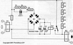
I have a solution which looks like this
WHICH ONE IS CORRECT LAYOUT?
THIS THE SCHEMATIC
Attachments
the RC timer is so badly affected by mains voltage variations that it MUST BE DISABLED if you intend starting up that style of amp with a Variac.I don't agree with Andrew on the RC timer - it is not greatly affected by supply fluctuation.
The RC should be designed to survive and do it's soft start job with maximum tolerance mains supply voltage.
The RC must then be checked for proper operation at lowest tolerance mains supply voltage. An improperly design RC timer may not trigger on lowest voltage or may not survive highest voltage or may delay the relay bypass such that the resistor ballast overheats. In this situation NTCs give a lot more safety to the soft start performance.
that is not the whole story.Lengthening the time delay allows the thermistor to reach its lowest impedance, therefore it will be easier on the relay contacts.
The NTC starts cold with high resistance.
A transient current passes through and starts heating the NTC, the resistance falls. The transformer has started up. The transient is over. The thermistor passes less current and thinks about starting to cool slightly, when it gets another burst of current as the rectifiers start charging up the smoothing capacitance. The NTC heats up slightly and the capacitors charge.
The NTC resistance has gone down for this initial fast charge of the caps.
Now the charge current falls and continues to fall. The NTC cools in response to this falling current. The NTC resistance rises and continues to rise towards it's cold to warm resistance.
If the capacitors are 95% charged in 1second from start up and the RC timer holds the relay open for 1.1s then the NTC resistance will be back up to a warm temperature value.
This will be no worse, nor better, than if a resistor of that value was in circuit.
Consider what voltage is across the closing bypass relay contacts @ 100ms after start up and @ 1000ms after start up and consider what difference there is in those voltages whether resistors are used or NTCs are used.
When do the contacts in the relay wear/erode?
During the spark duration across the opening contacts. Not during the closing. during closing there is a tiny amount of spark but that spark does not initiate until the gap between the contacts is so small that the air gap arcs (creating near instantaneous heating of the arcs ends). But the contacts are closing and the arc gets snuffed out during the last few us of the closing action. This arcing is very different from the spark erosion arcing that happens when the contacts are opening. During this opening phase the NTC has no influence on what voltage appears across the bypass relay contacts.
Last edited:
Andrew , I have considered (and tested) all failure modes with the RC/NTC setup. The tests were with a self powered (separate 12Vac trafo) RC/relay powered after the thermistor.
#1 - full relay - driver failure : thermistor will run amp independantly , even if it was <1R (hot) this still enough to protect from the next inrush event (if one did occur ).
).
#2 - RC does not discharge fast enough (double switch throw) , PS will still be partially active preventing PS cold state inrush. Mine discharges much quicker than it charges .1 sec discharge - 2-3 second turnon.
#3 - complete NTC failure , dead amp - RC/relay is not powered. I had a 20 year old NTC burn up , the oxide deteriorates after a couple decades. It arced at the lead , vaporized ... creating an open circuit. Old CRT degausser circuits would do this after a decade , always. No fire hazard.
I am about to make a full AC "package" (RFI - softstart) and separates. No unsafe aspects to note after 1000's of events.
NTC is smaller , cheaper $2.00 , simpler (1 component) I attach mine with fastons (easily replaceable. Resistors for my 1KVA would cost $8-10 and take up twice the PCB real estate. Genesis stealth amp used 10A NTC , it lasted 21 years.
PS - I can actually hear my 1KVA "inrushing" for 500ms with a cold start , that is why I chose my RC of 2 sec. + .
OS
#1 - full relay - driver failure : thermistor will run amp independantly , even if it was <1R (hot) this still enough to protect from the next inrush event (if one did occur
).#2 - RC does not discharge fast enough (double switch throw) , PS will still be partially active preventing PS cold state inrush. Mine discharges much quicker than it charges .1 sec discharge - 2-3 second turnon.
#3 - complete NTC failure , dead amp - RC/relay is not powered. I had a 20 year old NTC burn up , the oxide deteriorates after a couple decades. It arced at the lead , vaporized ... creating an open circuit. Old CRT degausser circuits would do this after a decade , always. No fire hazard.
I am about to make a full AC "package" (RFI - softstart) and separates. No unsafe aspects to note after 1000's of events.
NTC is smaller , cheaper $2.00 , simpler (1 component) I attach mine with fastons (easily replaceable. Resistors for my 1KVA would cost $8-10 and take up twice the PCB real estate. Genesis stealth amp used 10A NTC , it lasted 21 years.
PS - I can actually hear my 1KVA "inrushing" for 500ms with a cold start , that is why I chose my RC of 2 sec. + .
OS
Last edited:
During this opening phase the NTC has no influence on what voltage appears across the bypass relay contacts.
I saw no arcing either way with 2 huge spotlights hooked to my 75-0-75V supply. I saw the lights flicker as I shut off (voltage difference / relay to NTC) then the lights slowly dimmed.
Would a small transient bypass across the relay contacts help any? I've seen this on OEM's.
OS
Last edited:
What happens when you switch off?
Which switch opens to cut off the current flow?
Which switch contacts will suffer spark erosion?
When will the bypass relay open?
Is there any current flowing across the bypass relay contacts when the relay de-activates?
What is the voltage across the opening contacts of the bypass relay after they have just started to open?
Neither the NTC nor the Resistor has any influence on the opening contacts of the bypass relay.
BTW,
I gave an earlier version of this and no one came back and said I am imagining a new work of fiction.
that is not the whole story.
The NTC starts cold with high resistance.
.
There are some points you are not mentioning.
One, the thermistor passes the initial inrush current at that higher impedance and it immediately gets hot. How hot? How low is the impedance at that point? That depends on the rating of the part and the size of the transformer.
Two, it doesn't cool quickly, certainly not in the time frame you are saying. After the inrush current for the transformer, the cap bank starts to charge up - current once again goes up, and the impedance of the thermistor drops even further. I believe at this point, it is quite a lot less impedance than the similar size resistors. This is the relay contact advantage. Though very small (the voltages involved are no where near the contact ratings of even a small relay), there is less current for the relay to pick up.
Three, this all takes place in 2-3 seconds. The thermistor is still quite warm 10 to 20 seconds after the start up event.
For me, there is no contest. The thermistor is clearly the better choice. It is designed and manufactured this purpose.
As you saw , I retracted the first part of my last statement. When you open the mains switch , both the relay and the switch will "share" the difference as the supply discharges. I still have never seen ANY arcing at the relay. With no softstart on my small unit , I have a clear auto aftermarket switch and a small arc with turnon. At normal use , I see no arc at turnoff . This would seem to be a large trafo only issue as the small one is 200VA.
OS
OS
What happens when you switch off?
Which switch opens to cut off the current flow?
In mine, the on/off switch breaks mains AC before the softstart. This is instantaneous. The relay opens a few mS later - it breaks no AC current.
I agree.For me, there is no contest. The thermistor is clearly the better choice. It is designed and manufactured this purpose.
But I am a mean Scotsman that lives up to our reputation.
Suitable NTCs for 240Vac are expensive, much more expensive than bulk buy 5W WW resistors.
But I don't think it is a competition.
The question was about relay contacts and whether they deteriorate and whether that deterioration is lessened with NTCs compared to using similar value resistors.
BTW,
we need two series connected CL60 to give us 20r of cold resistance for starting a 240Vac transformer. That would require a higher value fuse than when using 60r of resistance. I would not consider using 6off CL60 in series, simply due to cost. But 6off 10r 5W @ 15p are cheaper than one CL60.
Last edited:
I've held my fingers on my NTC , with one inrush event (1/2 sec) It will just get warm to the touch and cool a few seconds later.Only If I cycle 2-3 / 10 second inrushes will it get hot to the touch. It cools in 10 seconds or less. hot = <1R cold = 20-25R. Still , the best solution is the one we have with the small trafo. yes , now that I think about it ... just the switch would see the arc , but it would be small at normal PS load.
I use this one on all my 6 monster amps. ($1.93)http://www.epcos.com/inf/50/db/icl_09/ICL__B57364__S364.pdf (16A -1R unit) I never considered the series (256V rating in the PDF) issue for 240 mains. Just one 20R resistor @10- 20W ($4.13) costs more than 2 of the above NTC.
OS
hot = <1R cold = 20-25R. Still , the best solution is the one we have with the small trafo. yes , now that I think about it ... just the switch would see the arc , but it would be small at normal PS load.I use this one on all my 6 monster amps. ($1.93)http://www.epcos.com/inf/50/db/icl_09/ICL__B57364__S364.pdf (16A -1R unit) I never considered the series (256V rating in the PDF) issue for 240 mains. Just one 20R resistor @10- 20W ($4.13) costs more than 2 of the above NTC.
OS
Last edited:
John - sorry if that sounded a bit picky - no, the intent was to eek out the design and performance issues of each option so that a better understanding can be gained. There is often benefit in working through each option, and even better to have comparisons, and many posters contributing their views. Sometimes a topic just gets a quick nod, with a cursory amount of detail presented.
I'm with you Tim. It's always good to get lots of input and sort through it, making choices based on the pros and cons of each method.
The first soft start I built was the one Rob Elliott has on his website. For me, at the time, this was a major project and TBH, at first it didn't work (bad things then happened). To this day, I'm not sure if it worked properly or not, after I fixed it.
I set out to simplify and heard about thermistors. I decided to replace the ESP soft start with a single SL 32 thermistor, thinking this is much simpler and at least I know it works. Before I could do that I had the idea that I could use the thermistor in place of the (exploding/burning) resistors and increase the time delay on the relay.
yes,The relay opens a few mS later - it breaks no AC current.
The bypass relay does not break any current when the equipment is turned off.
The bypass relay does not suffer spark erosion when the contacts open.
The NTC has no influence on the voltage across the contacts of an opening bypass relay.
The mains ON OFF switch will always be a different set of contacts from those in the bypass relay.
Only if the bypass trigger circuit went faulty would the bypass try to open when power was still applied.
your pricing is quite different.Just one 20R resistor @10- 20W ($4.13) costs more than 2 of the above NTC.
OS
I imported my 10r 5W ww from the States - 1000off for ~$200 + carriage combined with another order. I offered them to UK Members for their soft starts and dummy loads, but got only one enquiry.
CL60 and equivalent are usually around £2 each.
Practicality sometimes wins for each new project. I've just built a resistor limiter - but I had some 51R 9W Vitrohm KH, so I wanted to go through the design of the surge capability - which seems ok on paper. However I really should capture a turn-on waveform to check current waveform and relay operate time (I like the simplicity of the relay coil = mains voltage method). The amp is a 200W valve, so I will also have a bit of heater turn-on energy as well as main filter cap start up.
It is worth noting that if the dominant energy surge is in to filter capacitors, then half C x V squared will be the energy passed through the resistor/thermistor. Some thermistors (for switchmode) give a nominal max capacitance (based on rectified mains) for a given thermistor type - which is related to the transient energy dumped in the thermistor and max thermistor temperature reached due to the transient (as compared to designing the thermistor to handle the max continuous ampcurrent, which is more a thermal equilibrium issue for the thermistor). But amps are different from switchmodes due to transformer in-rush, and the effective resistance into the caps is higher (due to transformer windings).
I'll look around to see what NTC's I have, as a measurement comparison.
I'd also add some caution to interpreting thermistor temperature from touching - it can take some time for a high internal temperature (from a short transient) to transfer out to the case surface. And if the duty cycle is low (ie. multiple activations) then the impression may well be that the thermistor doesn't get too hot, and that it cools down quickly.
Ciao, Tim
I'll add a lot of caution.I'd also add some caution to interpreting thermistor temperature from touching
The NTC is at mains voltage !!!!!!!!!!!!!!!!!!!!!
Mine are coated with thermoplastic (dipped). Here in the states , 120V is doable  I have been shocked "all the way" by it. Not that I want to flirt with death, but it has happened. On euro 220-240 mains (and our 240 systems) I don't touch. I got bit by 240 once ... WOW. The 150VDC on my big amps would most likely let the magic smoke out of your body ... I have seen a 14 gauge wire atomize instantly (explode). That is why I have red and blue LED's on all my big PS's , if they are on ... I will not touch.
Rod elliots... "one flash and your ash" is quite truthful.
OS
I have been shocked "all the way" by it. Not that I want to flirt with death, but it has happened. On euro 220-240 mains (and our 240 systems) I don't touch. I got bit by 240 once ... WOW. The 150VDC on my big amps would most likely let the magic smoke out of your body ... I have seen a 14 gauge wire atomize instantly (explode). That is why I have red and blue LED's on all my big PS's , if they are on ... I will not touch.Rod elliots... "one flash and your ash" is quite truthful.
OS
Since surplus relays are cheap, and may come in several poles and double throw, I would use one or more of the "normally off" contacts to discharge the PS caps through a resistor. One issue is the mixing of AC and DC contacts on the same relay. Don't know if this is allowed.
Also, to prevent rapid cycling of a NTC or speaker pulses during flickering power conditions, such as during a storm, use a momentary-on push button switch and mains relay instead of an on-off switch. Use the push button switch to energize the mains relay coil, and further energize the coil via its own contacts so that the relay stays on after the push button is released. If power dies, the relay kicks out, and won't reenergize until the push switch is pressed again. You'd have to find a quiet relay coil for the AC coil, or convert to DC with a very light filter cap to keep it from holding the relay closed after power outage. Of course, you'd need another switch to de-energize the coil to manually turn it off when desired.
Also, to prevent rapid cycling of a NTC or speaker pulses during flickering power conditions, such as during a storm, use a momentary-on push button switch and mains relay instead of an on-off switch. Use the push button switch to energize the mains relay coil, and further energize the coil via its own contacts so that the relay stays on after the push button is released. If power dies, the relay kicks out, and won't reenergize until the push switch is pressed again. You'd have to find a quiet relay coil for the AC coil, or convert to DC with a very light filter cap to keep it from holding the relay closed after power outage. Of course, you'd need another switch to de-energize the coil to manually turn it off when desired.
Last edited:
- Status
- This old topic is closed. If you want to reopen this topic, contact a moderator using the "Report Post" button.
- Home
- Amplifiers
- Solid State
- SOFT START FOR POWER AMPS