My experiments with bipolar transistor circlotron amplifiers are being frustrated because I can't seem to figure out how to get the amplifier to bias properly. With a standard solid state amplifier design, one uses the Vbe multiplier to get a defined voltage at the output devices base and the quiescent current is set by the drop across the emitter resistor, but in trying to set something similar up with a circlotron, I can never get it to work out properly. Any advice or examples would be much appreciated!
Basically you first have to understand how the circlotron works.
You have two options: let's call them Thevenin and Norton.
In the Thevenin case, you have an auxiliary supply referenced to the emitter of the top transistor, feeding the base through a bias resistor.
The lower transistor simply has a resistor between base and emitter.
The driver transistor is connected between the bases, and diverts a controlled fraction of the bias current from the top transistor to the bottom one.
Normally, under quiescent conditions, exactly half of the bias current is passed through the driver.
In the Norton circuit, both transistor have identical E to B resistors, and a CCS supplies twice the bias current to the top transistor, and as in the previous case, half of this current is taken by the driver to the base of the bottom transistor.
Both approaches are equivalent from a theoretical standpoint, but I find the Norton version much easier to apply practically.
Here is a practical example:
http://www.diyaudio.com/forums/atta...logy-no-feedback-classab-buffer-unigabuff.gif
It is a bit unusual, because it is implemented as a unity gain buffer, but if you make Q4 NPN, it becomes the standard circuit.
The current source is Q3, and it has to compensate thermally the output transistors via D1 or D2, the other serving as a self compensation.
In addition, this circuit has a servo-controlled Iq via Q5 and Q6, but conventional emitter degeneration is also usable.
Look for a SUMO NINE or NINE+ schematic. It's a solid state circlotron from the late 70s/early 80s. I don't know the details of your amp but maybe you'll get some ideas from the SUMOs.
Craig
Craig
Audio amplifier - Google Patent Search
In practice the two cathodes are tied together and a variable resistor is returned from the cathodes to ground.
In practice the two cathodes are tied together and a variable resistor is returned from the cathodes to ground.
Last edited:
Basically you first have to understand how the circlotron works.
You have two options: let's call them Thevenin and Norton.
In the Thevenin case, you have an auxiliary supply referenced to the emitter of the top transistor, feeding the base through a bias resistor.
The lower transistor simply has a resistor between base and emitter.
The driver transistor is connected between the bases, and diverts a controlled fraction of the bias current from the top transistor to the bottom one.
Normally, under quiescent conditions, exactly half of the bias current is passed through the driver.
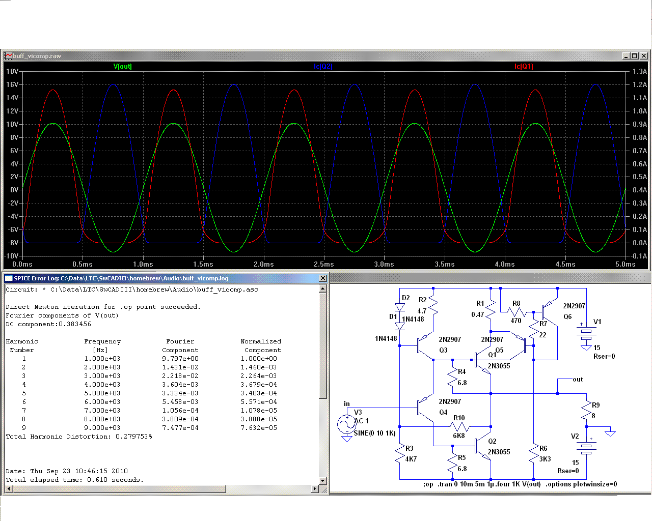
Thank you for your reply. I'm a little unclear on how this would work - for example, in the circuit you posted, let's say I remove the bias stabilization circuit consisting of Q5 and Q6 and put in place emitter resistors in each power transistor. In that case the current from the current source is going to zip down through Q3 and through R4, and through Q4 and R5. There's no way to "force" the current to go into the bases of the power transistor. In that case I don't see how one would set a quiescent bias point for the output transistors using such a current source.
Part of the current provided by Q3 will go into R4, and the rest will be diverted by Q4 to R5.
When the circuit is properly adjusted, the voltages across R4 and R5 will be equal and just sufficient to reach the Vbe of the output transistors.
The quiescent current will be set by the common current generator Q3, which is why it has to be thermally coupled to the output transistors.
Q4 manages the way the total current is shared between the output devices: if it conducts less, Q2 will be completely off, and the excess current will flow into the base of Q1 (the value Vbe/R4 is constant), making it conduct more.
It also works in the opposite direction.
interesting topic. I recall to a special circuit in the German magazine "Funkschau" (diy power amp project approx. 1965) concerning bias stabilization for 2N3055 Circlotron. In the next time I will check old stuff and if I find this article, I will report about that circuit;
check out also this:
http://www.diyaudio.com/forums/pass...clotron-jfet-input-buffer-opa1632-2sk135.html
http://www.amplimos.it/images/SUMO.pdf
SUMO Line
http://www.diyaudio.com/forums/soli...-names-commercial-solid-state-amplifiers.html
Are there commercial amp products with the topology according the so called Norton circuit about follow URL?
http://www.diyaudio.com/forums/atta...logy-no-feedback-classab-buffer-unigabuff.gif
Last edited:
from the good known push-pull buffer technology with NPN/PNP BjT's the typical value for the idle current must be between 15mA and 50mA for each power device - mostly 25-30mA.
Can I realize the same idle current values (and the same crossover distortion values at the same time) by this both circlotron topologies?
To bring D1 and D2 in thermal contact with the heatsink of output power devices it would be from the mechanical point a good way to create this diodes from a TO126 BjT like BD139. Are there electrical disadvantage in this case?
In the attachement Elvee's circuit with theory of operation from his post's here so as DC conditions
Attachments
Last edited:
I think so.from the good known push-pull buffer technology with NPN/PNP BjT's the typical value for the idle current must be between 15mA and 50mA for each power device - mostly 25-30mA.
Can I realize the same idle current values (and the same crossover distortion values at the same time) by this both circlotron topologies?
The classic circlotron (all NPN, including the phase splitter) works essentially in a common emitter configuration, very much like older topologies using transformers.
But for those topologies, the optimum quiecent current is in the same range as the more modern, complementary ones
To bring D1 and D2 in thermal contact with the heatsink of output power devices it would be from the mechanical point a good way to create this diodes from a TO126 BjT like BD139. Are there electrical disadvantage in this case?
Note that only one of the diodes has to be in thermal contact with the output devices: coupling both of them would lead to overcompensation.
And the other one is needed to compensate for CCS itself, Q3.
A TO126 seems nice for this function. And if it is a large area transistor, the current density will be small, causing a small overcompensation, which is probably desirable to overcome imperfect thermal coupling.
go to post # 45 aboutinteresting topic. I recall to a special circuit in the German magazine "Funkschau" (diy power amp project approx. 1965) concerning bias stabilization for 2N3055 Circlotron. In the next time I will check old stuff and if I find this article, I will report about that circuit;
http://www.diyaudio.com/forums/soli...no-feedback-classab-buffer-5.html#post2337770
Automatic/Self Biasing Approaches for Circlotrons wanted
about
http://www.diyaudio.com/forums/pass...as-automatic-self-biased-overview-wanted.html
there are listed several approaches to make it easy getting stable idle current without adjust (or at least a stable value after first try of adjust)
I think the follow listed approaches must actually be easy to convert for the circlotron topology.
1) William T Chater's Bias Control for Power Amplifier
Bias control for power amplifiers
from post #40 about
http://www.diyaudio.com/forums/soli...tter-audio-non-complements-audio-power-4.html
2) Automatic Bias without external bias adjustment - Linear Tech. LT1166 chip
http://www.diyaudio.com/forums/solid-state/1573-linear-tech-lt1166-chip.html
3) AUTOMATIC QUIESCENT CURRENT CONTROL FOR THE POWER
TRANSISTORS WITHOUT TEMPERATURE SENSE ELEMENTS
http://www.st.com/stonline/books/pdf/docs/1472.pdf
Are there any experiences in this matter ?
Chater's patent United States Patent US5055797 (expired) looks quite easy to do and could be done with an opamp on each FET in a grounded output stage giving good control for unmatched parts.
The Sumo 9 is an interesting sliding bias circuit.
The Power was a more conventional bridge amplifier, not a circlotron. See the Ampzilla III in the Audio Amateur for details.
The Power was a more conventional bridge amplifier, not a circlotron. See the Ampzilla III in the Audio Amateur for details.
The SUMO GOLD was the high power circlotron. I have the schematic for the output section, it's like the NINE but with "more power" as Tim Allen would say. Unfortunately it is the size of the original blueprint, huge by huge. Sumo was gone by the time I realized I didn't have the front end. 🙁
Craig
Craig
"Sumo was gone by the time I realized I didn't have the front end."
I can guess as to what he would have done, cross-coupled dual differential inputs and Vas for the front end, just like the Andromeda, driving the circlotron output stage. Look at the Sumo 9+ to figure out the bias details. JB is not forthcoming on info for the early Sumo gear.
I can guess as to what he would have done, cross-coupled dual differential inputs and Vas for the front end, just like the Andromeda, driving the circlotron output stage. Look at the Sumo 9+ to figure out the bias details. JB is not forthcoming on info for the early Sumo gear.
Thank you. By post #40 aboutChater's patent United States Patent US5055797 (expired) looks quite easy to do and could be done with an opamp on each FET in a grounded output stage giving good control for unmatched parts.
http://www.diyaudio.com/forums/soli...tter-audio-non-complements-audio-power-4.html
you will find a cover image to the associated AE issue, where you will find the according diy project therefore.
Translating this topology for a circlotron must be actually possible.
Who knows, how the bias control work from the genuine version from follow Thorens topology:
http://www.diyaudio.com/forums/tubes-valves/213159-thorens-tem-3200-clone.html
Last edited:
The Sumo 9 is an interesting sliding bias circuit.
The Power was a more conventional bridge amplifier, not a circlotron. See the Ampzilla III in the Audio Amateur for details.
There are various SUMO schematics, but on the web obviously no longer available. In the attachment various versions:
Attachments
Last edited:
The circlotron is notionally equivalent to a 'fully complementary' amplifier with more ideal complements. Everything that applies for biasing of whatever device is used in the vonfiguration, applies here as well.
The trisky thing with a circlotron is that you can't really easily draw it and make it easy to see what the idea is 🙂 and the floating supply does confound a bit.
The trick is to look at the topology as a differential in - differential out amplifier, and in this manner it does not really have a 'ground' - it's all floating. Bias becomes more easy to figure out once a ground node is made by creating a center point for the output, normally using a simple resistive divider. If you look carefully, any bias voltage/current from this point to the inputs of the circuit (depending on device used) will appear as a bias voltage/current for the circuit, equally for both inputs. Since the front end of an amplifier usually has a ground as is not floating like the rest of the circlotron, it usuallyhas it's own power supply, with a ground node. The voltage or current applied from the input stage ground node to the 'ground' point of the circlotron output is the bias for the devices in the circlotron. Normally it needs to be applied just the same way as usual, taking care of thermal coupling and tracking etc if necessary for the device.
The Sumo 9 is amongst other things based on a patent by it's designer J. Bongiorno which uses the actual Vbe of the output transistors to establish a bias for themselves, essentially offering thermal self-tracking.
- Status
- Not open for further replies.
- Home
- Amplifiers
- Solid State
- Biasing schemes for bipolar transistor circlotrons