hi, i decide to make sr 150 confirm.please tell is everything ok in your pcb?tell more about sound quality and give me advice and any kind of trouble.i am asking because i will make sr150 on your pcb.thank you for sharing.GIF , pdf and sprint-file:
Last edited:
post1752.
The T1 & T2 drivers are very likely to have different Vgs.
Do the values of R3 & R4 need to be adjusted so that they pass the same current?
Or do we just accept that the 2k2 will pass different currents.
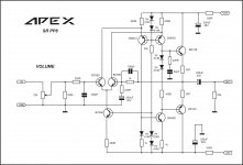
Design in post #1752 is mine so I consider that I can answer you.
T1 and T2 have different values c_iss, therefore, those different R_gate values.
They also have diferent threshold voltages, but R_gate versus R3 or R4 have minor deviations in voltage divider terms of speaking (cca 2-3 %)
In tests conducted by 44250 on the project LME48830 Hybrid, whit identical output power stage , which is also my design,
we have come to conclusion that with the all-over compensations we made
(... in NFB, in II.pol compensation between COMP pin and M_out of V_be multi - LME49830, in gate comp ...)
with the input square waveform signal @15KHz, the best result was with the given R_gate values.
so we come into final trimming with largest SR, smallest Settling time, with almost no Overshoot ... with no oscilations on "heavy loads" (8R//2uF) ...
R3 and R4 are primarily due to gate-charge and reduction in turn-off time.
Regards
Dragan100
hi, i decide to make sr 150 confirm.please tell is everything ok in your pcb?tell more about sound quality and give me advice and any kind of trouble.i am asking because i will make sr150 on your pcb.thank you for sharing.
those are the latest files,and an amplifier on video works on them. all changes i have done to make it work (values from two resistors on amplifier stage,and one in protect stage) were assigned on schematics. PDF of top layout and copper side are latest,feel free to make your amp on them.
only thing that might be different in your case is 560r 2W in series with relay coil and value of that resistor actually depends on coil resistance. my relay coil resistance is 400 Ohm and with 560r 2W i have about 15V on relay and i will not change it. yes it is a bit more than 12V but relay is not getting to warm and i believe that i have a better contact in it.
it works really nice in all sound ranges,and even with 3,3uF elco instead 10uF block on input it goes really deep on bass - i am nicely surprised!
Design in post #1752 is mine so I consider that I can answer you.
T1 and T2 have different values c_iss, therefore, those different R_gate values.
They also have diferent threshold voltages, but R_gate versus R3 or R4 have minor deviations in voltage divider terms of speaking (cca 2-3 %)
In tests conducted by 44250 on the project LME48830 Hybrid, whit identical output power stage , which is also my design,
we have come to conclusion that with the all-over compensations we made
(... in NFB, in II.pol compensation between COMP pin and M_out of V_be multi - LME49830, in gate comp ...)
with the input square waveform signal @15KHz, the best result was with the given R_gate values.
so we come into final trimming with largest SR, smallest Settling time, with almost no Overshoot ... with no oscilations on "heavy loads" (8R//2uF) ...
R3 and R4 are primarily due to gate-charge and reduction in turn-off time.
Regards
Dragan100
regards to my friends that i like to listen and read their posts,no matter on what forum : APEX and Dragan100!
") i learn each day from them...
i learn each day from them...APEX SR100 Studio Ref Amp
Won't be better to the make Q5 and Q6 into differential pair by tying the two emitter together?
In attachments you will find TinaTI simulation files,
SR150, SR150H and the latest variations SR150LBH LinearBipolarHybrid
with Mosfet at the output,
together with the complementary pair 1943/5200.
They are biased: mosfet@250mA, bipolars@cca 50mA each,
and must be closely matched for even current distribution.
At Mosfet gates is a linearisation stage in some current mirror variation
which design is from our forum member MacolaKG here at local forum DIY Audio Projects
The whole output stage is in the very strong local FB
and output stage curve parameter from such type output is pure line y = K * x,
The predrivers are biased also in ClassA@25mA,
Feel free to take a journey with doose files into simulation world and look at amps parameters...
Regards
Dragan100
Attachments
Design in post #1752 is mine so I consider that I can answer you.
T1 and T2 have different values c_iss, therefore, those different R_gate values.
They also have diferent threshold voltages, but R_gate versus R3 or R4 have minor deviations in voltage divider terms of speaking (cca 2-3 %)
In tests conducted by 44250 on the project LME48830 Hybrid, whit identical output power stage , which is also my design,
we have come to conclusion that with the all-over compensations we made
(... in NFB, in II.pol compensation between COMP pin and M_out of V_be multi - LME49830, in gate comp ...)
with the input square waveform signal @15KHz, the best result was with the given R_gate values.
so we come into final trimming with largest SR, smallest Settling time, with almost no Overshoot ... with no oscilations on "heavy loads" (8R//2uF) ...
R3 and R4 are primarily due to gate-charge and reduction in turn-off time.
Regards
Dragan100
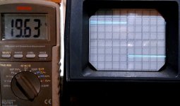
LME49830 Hybrid by 44250 square wave at input 19,5KHz,
output 8R//470nF
oscillogram in attachment: 5usec/div, 10V/div
It is almost optimal dumped, with avarage SR but stil in the range of 70-80V/usec,
the BW is in the range of -0,5dB@4,5Hz and -0,5dB@375KHz
phase is almost linear in audio spektrum with +2,5°@20Hz and -3,6°@20KHz
@AndrewT:
You can find that the simetry of waveform at the output is very good with doose diferent R_gate resistors and equal Rgs.
Also the input sq.wave is already slightly not perfect, so look at output, it just follows that signal...
Regards
Dragan100
Attachments
Last edited:
APEX SR150 is a great amplifier to listen,i can freely confirm that... today i will do some measurements,and than we will se what osciloscope has to say,and how it will confirm results from simulations.
no matter what osciloscope will say - it really sounds impressive in all stages,full of power and dynamics!
no matter what osciloscope will say - it really sounds impressive in all stages,full of power and dynamics!
Hi Apexaudio
Are you selling pcb or any of the stuff? I read through the first 15 pages and the last 3 pages. Seems like you just post your designs and encourage others to build it for free!!! I found your SR100/SR200 interesting. Just wonder whether you have plans to sell the pcb.
I can layout pcb, but it's going to cost more for small quantity. If you sell pcb, you can sell large quantity and I am sure you can sell to me much cheaper than I make my own.
I still going to read more of your posts here. I am just curious how is the sound of your SR100/SR200 compare to the normal complementary input LTP, symmetric VAS type designs detailed in Bob Cordell's book.
Last edited:
Is there any pcb for this preamplifier?SR Preamp
If you follow the many Apexaudio threads, Mile makes a point of saying he doesn't offer PCBs - period. Much of the threads are taken up with other guys efforts at etching from the artwork with various dry transfer aids and even hand drawn - true DIY!Anyone sells pcb for SR200 etc.?
I kind of figure it out, just want to confirm. Just curious why he spend so much time and not making any money.If you follow the many Apexaudio threads, Mile makes a point of saying he doesn't offer PCBs - period. Much of the threads are taken up with other guys efforts at etching from the artwork with various dry transfer aids and even hand drawn - true DIY!
I like part of the design, is the sound really that good compare to other really high end amps? Not trying to insult or anything, just curious as I only see the circuit.
I kind of figure it out, just want to confirm. Just curious why he spend so much time and not making any money.
I like part of the design, is the sound really that good compare to other really high end amps? Not trying to insult or anything, just curious as I only see the circuit.
I make money by creating my amplifiers but I do not want to use the forum for advertising.
Regards
I kind of figure it out, just want to confirm. Just curious why he spend so much time and not making any money.
I like part of the design, is the sound really that good compare to other really high end amps? Not trying to insult or anything, just curious as I only see the circuit.
it depends on with what you compare,off course - but i must say (again) that APEX is able to take the best possible from ordinary parts (transistors in first place) to get very interesting results. everything i did with APEX logo (and there is quite a lot of that) works stabile,has wide bandwidthand even a bit overcompensated (i believe from security reasons) it has nice responce to a square test with 8r load.
for example,his A23 was best on 8r60uH470nF square signal test out of five other (here on forum well known) designers amplifiers. how do they sound- that is individual for each one of us - off course,even APEX designes sound diferent between each other.
That's real DIYI make money by creating my amplifiers but I do not want to use the forum for advertising.
Regards
Congratulations Mr. Mile!
Thimios.
hi, i decide to make sr 150 confirm.please tell is everything ok in your pcb?tell more about sound quality and give me advice and any kind of trouble.i am asking because i will make sr150 on your pcb.thank you for sharing.
if you do an amplifier on my earlier files,you should pay attention on 2N5401 and his Hfe - it should be at least 250. is it enough you can check by measuring it´s Uce,it should be under 1V. if you don´t have it you can use another one,for example BC560C or BC516 but you must check pinout diference.
on files under this post there is PCB with BC516 placed instead 2N5401,and here is a part list for that version:
10r x6
47r x2
100r x3
1k x10
220r x9
2k2 x2
15k x2
22k x2
47k x1
100k x1
220k x3
360r (Rrel) x1
1r 2W x12
6k8 2W x1
4r7 2W x2
560r 2W x1
Relej x1
Osigurač-postolje x2 (FUSE)
LED 3mm x1
LED 5mm x1
2SA1943 x2
2SC5200 x2
MJE340 x2
MJE350 x2
2N5401 x1
2N5551 x3
2SC4793 x1
2SA1837 x1
BC516 x1
BC557 x2
BD139 x1
MPSA42 x1
MPSA92 x2
1N4007 x3
ZD15V x2
1N4148 x10
10pFx1
470pF x2
100nF63V x5
100nF100V x1
1nF63V x1
1uF 100Velk. x1
10uF50V-blok x1
100u25V x1
47u100V x1
220u25V x2
220u63V x4
470uF16V x1
Attachments
- Home
- Amplifiers
- Solid State
- Studio Reference Amplifier