Bob,
I see the Vbe multiplier as a disturbance in the VAS load (a nonlinear element). In this way, no need for an in itself aggravating bypass capacitor to improve high frequency distortion and transient response.
Another problem with the triple (when composed of devices with the same polarity) is an alarming rise in saturation voltage.
Hi WuYit,
There lurks nonlinearity in every part of a circuit that includes a semiconductor, so you may be technically correct. However, the key in engineering is understanding the relative size of the contribution compared to other similar contributions elsewhere. That is one of the reasons we do simulation, but simulation is not the only approach to sorting things out.
So, have you simulated the contribution of Vbe multiplier nonlinearity to that of an amplifier?
The rise in saturation voltage caused by an EF Triple is one Vbe. This is a reasonable price to pay for the far better performance. The output BJTs don't perform all that well when they get really close to the rail anyway.
Cheers,
Bob
I don't know how many times I've tried to lead people in this direction. I was able to use as little as 150R gate stoppers with the planer stripe mosfets; Cgd could reach over 2nf at Vds saturation!
BTW I can amplify at fairly low distortion over 400KHz with that amp.I attribute this mostly to the extra speed of the output stage due to more effecient filtering/damping of the perceived occilators within the mosfet.
Hi CBS,
These are good points you make about gate stoppers and oscillations. The key is to find the most effective way to kill the Q of parasitic resonances while minimizing the reduction in high-frequency performance.
Cheers,
Bob
Howdy,
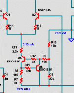
Without a base stopper the LED CCS is not stable either.I have found that the decoupling of the drivers/ccs and the choice of CCS is what gives stability in THIS triple. The CCS and what TYPE of CCS makes all the difference, as it does nearly all the work in the predriver stage. A 2Q CCS was not as stable as the red led version - too much gain. I'm sure with basestoppers on a 2Q I would be golden - but I like the warm glow of the 2 LED's .
Howdy,
Without a base stopper the LED CCS is not stable either.
False ! Would "not stable" refer to temperature or current ? Too broad of a statement to be valid. An LED CCS has a lower output impedance and is not as accurate (current wise) , so "less" stable would describe it. Temperature wise , the LED does well , compensating for the transistor's Vbe.
This leaves outright oscillation , very improbable as the only feedback is Re. I have never seen a LED CSS do this , I can't say the same for a 2Q CCS.
OS
Hi wahab,
MOSFETs are more friendly in some ways, and I like MOSFETs. However, they are often more prone to HF oscillations, as pointed out in my book. They are fundamentally faster than power output BJTs, and this is part of the reason for an increased tendency to HF oscillation. Indeed, much larger gate stopper resistors are usually employed with MOSFETs, even when they are not paralleled. We sometimes see 470-ohm gate stoppers with laterals!
In my MOSFET power amplifier with error correction design, I was able to use gate stoppers as small as 47 ohms with verticals, but my use of gate Zobel networks permitted that.
Cheers,
Bob
Hi , Bob
Dont know exactly about the Hexfets , but for Hitachi laterals , unless
the layout or the design or even both are badly executed, values
as low as 10R can be implemented, as done by Hitachi themselves
in a commercial amp.
Personnaly, i use three pairs of Hitachi s lateral in most of my amps,
with 100R gate stoppers , but i admit that i did choose such a value
more by some cautious and also gregarious reflexe , since it s generaly
the lowest value used in many designs.
Indeed, increasing the base stoppers value also dramatically reduce
phase margin past a relatively low value that is well below the designers
habits with laterals fets.
cheers,
w
Very likely, for more than one reason.So just about all the DIYA AB amps oscillate ?
A bad and regrettable practice. Do base stoppers complicate things considerably?90% use either diode or led referenced CCS's without a stopper.
Do base stoppers complicate things considerably?
WuYit, with a CCS , a base stopper is counterproductive...
Very likely, for more than one reason.
A bad and regrettable practice. Do base stoppers complicate things considerably?
No , they don't. And I use them in my high beta 2Q ccs for the IPS.
OS
Attachments
Last edited:
I'm not criticizing your design, on the contrary. For driving a subwoofer, the amplifier`s ability to deliver current and provide electrical damping are of primary importance. This leads us to a design like yours, a dedicated constant voltage amp with bipolar Darlington output in class AB. I just don`t see the need for the triple.
I'm jumping into this conversation late, but the major point of a triple (EF or otherwise) is to lessen the load on the VAS, lowering distortion. Bob Cordell's book goes into this in very high detail.
I'd also like to point out how lucky we are to have the author available right here for discussions. I'm still working my way through the book, but it's been extremely useful so far. It's a great resource.
I'd also like to point out how lucky we are to have the author available right here for discussions. I'm still working my way through the book, but it's been extremely useful so far. It's a great resource.
The lower overall Gm of the lateral devices reduces their effective Ft. Verticals are inherently faster.Hi , Bob
Dont know exactly about the Hexfets , but for Hitachi laterals , unless
the layout or the design or even both are badly executed, values
as low as 10R can be implemented, as done by Hitachi themselves
in a commercial amp.
I just don`t see the need for the triple.
Cascoded VAS is high impedance - EF2 loads it down , even with normal loads. SO , either EF lateral or triple. In simulation , that luxman voltage stage does .01-.02% with an EF2 ,but does < .0001 to .0006% on any flavor of triple.
As far as sound , have you heard a leach amp do drums .. woweeee !
OS
I'm jumping into this conversation late, but the major point of a triple (EF or otherwise) is to lessen the load on the VAS, lowering distortion. Bob Cordell's book goes into this in very high detail.
I'd also like to point out how lucky we are to have the author available right here for discussions. I'm still working my way through the book, but it's been extremely useful so far. It's a great resource.
Hi Stormrider,
Thanks for the kind words about my book, and I hope you continue to enjoy it as you read further.
The Triple really does make a difference, even when a more conventional non-cascoded VAS is used. Many do not understand the relatively high current demands that a loudspeaker can place on an amplifier, especially many of those produced that cheat on sensitivity and have impedances that may dip to 2 ohms or worse. When one does the numbers, things can quickly get ugly, especially when one considers beta droop in the output transistors and even the drivers. Output transistor beta can droop to 10 in some cases, causing the driver, in turn, to have to supply a lot of current, which may even cause its beta to droop. You could end up with a double with net beta of perhaps only 300. Driving a 4 ohm load you get only 1200 ohms as seen by the VAS. At this point, the concern should be obvious.
People also need to bear in mind that the mere changing of net output stage beta with signal current can be a significant source of distortion. The higher the net beta, the smaller the effect of a given percentage change in beta with signal.
Cheers,
Bob
I'm not criticizing your design, on the contrary. For driving a subwoofer, the amplifier`s ability to deliver current and provide electrical damping are of primary importance. This leads us to a design like yours, a dedicated constant voltage amp with bipolar Darlington output in class AB. I just don`t see the need for the triple.
Hi WuYit,
Amplifiers with high current capability are not just needed for subwoofers. The Triple is important in delivering high current effortlessly, and greatly improves performance across the band. If you do some simulations, you'll see the difference immediately. If you build and measure an amplifier, you'll readily see the difference. One of the biggest mistakes designers make is in too heavily loading the VAS. In MOSFET amplifiers, for example, some designers see the supposedly infinite current gain of the MOSFET and think it is OK to directly drive them from the VAS, with no driver buffering the signal. Big mistake.
In most cases, the difference between a double and a triple is one pair of TO92 transistors, or maybe one pair of TO 126 transistors. One of the most cost-effective improvements one can make to a power amplifier.
Bart Locanthi popularized the Locanthi T circuit triple more than 40 years ago, and many great amplifiers have followed suit since then.
Cheers,
Bob
In MOSFET amplifiers, for example, some designers see the supposedly infinite current gain of the MOSFET and think it is OK to directly drive them from the VAS, with no driver buffering the signal. Big mistake.
I can't imagine perceiving Cdg and it's effect on the voltage stage any different than with a overloaded "droopy" EF2.
Either output stage solution accomplishes high current , no- loading design goals. The trade-off is in the V MOSFET's simplicity but higher cost vs. the BJT's lower cost. I have built both and they are audibly very similar. In either case , we just want to "hear" the unloaded voltage stage through as transparent a current stage as possible.(an "ideal" current amp)
As I said (last post) , any decent sounding IPS/voltage stage will both simulate and sound better , especially at LF ... on either of the above output stage solutions. You can also run your voltage stage @ 3-5ma , eliminating thermal considerations plus greatly increasing MTBF - a "free" side benefit.
OS
- Home
- Amplifiers
- Solid State
- Bob Cordell's Power amplifier book

