Bob,
there are distinctive differences between local feedback, feedback through two devices and feedback through multiple devices, where each device affects the loop and each device is affected by the loop. The time delay increasing with the number of stages hinders a precise control and does big damage. The subject would deserve a whole chapter of its own.
there are distinctive differences between local feedback, feedback through two devices and feedback through multiple devices, where each device affects the loop and each device is affected by the loop. The time delay increasing with the number of stages hinders a precise control and does big damage. The subject would deserve a whole chapter of its own.
Bob,
there are distinctive differences between local feedback, feedback through two devices and feedback through multiple devices, where each device affects the loop and each device is affected by the loop. The time delay increasing with the number of stages hinders a precise control and does big damage. The subject would deserve a whole chapter of its own.
Hi WuYit,
More generalities, I'm afraid. If you write that chapter, you'll have to be a lot more specific. Sounds like you are just repeating things you have read about. What actual experience do you have?
Cheers,
Bob
Hi Pete,
.....
What's important is that a good circuit gets explained and popularized. I also cringe a bit when a properly executed version of the old Linn circuit is referred to as the Blameless.
...
Bob
A bit on the Lin circuit and patent:
http://www.diyaudio.com/forums/solid-state/30439-amplifier-topologies-20.html#post572665
Oral History Lin Index RCA Germanium Transistors Audio
Schematic is on page 7 here:
Oral History Lin Page7 RCA GermaniumTransistors Audio
I don't see Lin's topology as being very, if at all, similar to Self's Blameless.
I'd say that the Blameless borrows much more from the JE-990 and most likely the 990 borrows from other OP amps so who knows. What I find significant about Self's work is that he systematically "peeled" away the layers of distortion by identifying the source and finding a solution for each one - often simple solutions. This is what he means by blameless as I understand it.
More stages ... problems??
Hinders precise control ? I find just the opposite ...( below 1 - not a LT "trick").
Adding more stages can be advantageous if properly implemented. The "bad" local loops can be dealt with (rail feedback loop on a triple for example - figure 10.15 in the book). I think the "DBT" itself is a local loop , a good one that works.
A question ? Would a triple like the "DBT" benefit from a speedup cap at the driver Re ? Would not the Diamond drivers/CCS's sweep the carrier charges from the OP's ? I left the space for the cap just in case (below 2 - almost ready to go - luxman/DBT).
If you look at the PCB , P192 is as "real world" as it gets - just curious , did you build one ? It works EXACTLY as advertised !
OS
HUH ???there are distinctive differences between local feedback, feedback through two devices and feedback through multiple devices, where each device affects the loop and each device is affected by the loop. The time delay increasing with the number of stages hinders a precise control and does big damage. The subject would deserve a whole chapter of its own.
Hinders precise control ? I find just the opposite ...( below 1 - not a LT "trick").
Adding more stages can be advantageous if properly implemented. The "bad" local loops can be dealt with (rail feedback loop on a triple for example - figure 10.15 in the book). I think the "DBT" itself is a local loop , a good one that works.
A question ? Would a triple like the "DBT" benefit from a speedup cap at the driver Re ? Would not the Diamond drivers/CCS's sweep the carrier charges from the OP's ? I left the space for the cap just in case (below 2 - almost ready to go - luxman/DBT).
If you look at the PCB , P192 is as "real world" as it gets - just curious , did you build one ? It works EXACTLY as advertised !
OS
Attachments
Adding more stages can be advantageous if properly implemented. The "bad" local loops can be dealt with (rail feedback loop on a triple for example - figure 10.15 in the book). I think the "DBT" itself is a local loop , a good one that works.
A question ? Would a triple like the "DBT" benefit from a speedup cap at the driver Re ? Would not the Diamond drivers/CCS's sweep the carrier charges from the OP's ? I left the space for the cap just in case (below 2 - almost ready to go - luxman/DBT).
OS
A triple EF is not a trivial stage when dealing with AC signals.
What is gained in current gain might as well be lost in voltage
drops and reduced perfs , thanks to the base stoppers resistors.
I often see resistors like 100R for the second device and values
at about 2.2R for the following and final stage.
Such values are often well inadequate when using high frequency devices,
and overall, a classic double EF using high gain devices seems to me a smarter choice
for those who prefer BJTs over the much more friendly Mosfets..
Certain high impedance voltage stages are best "serviced" by a triple. The standard "LIN" (ccs) stage is very comfortable running hot at 12-15ma , as is a leach type push pull. Both work well with an EF2. My LED biased hawksford cascode VAS runs best at 5-6ma. I ran it for 8 months on a EF2 , sounded good at low-mid levels , but lost it's goodness when ran hard. Not so on a triple.
So what if I lose 5V on my rails , I have 68-0-68vdc .... Also , my board can take boosted rails if I want that 5v back. I feel a 120v p-p capability will satisfy most demands - even a high crest factor source. BTW , the DBT only loses 2.1V off the rails and the hawksford w/ green led's another 2.4 = 4.5V. nothing to cry over.
Reduced performance ?? ... come on !!!! (below) I have never achieved 120v p-p @ 2R with 27ppm THD20.
OS
So what if I lose 5V on my rails , I have 68-0-68vdc .... Also , my board can take boosted rails if I want that 5v back. I feel a 120v p-p capability will satisfy most demands - even a high crest factor source. BTW , the DBT only loses 2.1V off the rails and the hawksford w/ green led's another 2.4 = 4.5V. nothing to cry over.
Well inadequate ?? They seem pretty standard , OEM ,classic pro-amp , and DIYSuch values are often well inadequate when using high frequency devices,
Reduced performance ?? ... come on !!!! (below) I have never achieved 120v p-p @ 2R with 27ppm THD20.OS
Attachments
Well inadequate ?? They seem pretty standard , OEM ,classic pro-amp , and DIY
OS
Great, OS , but what about stability ?..
So far, when simulating triple EFs, without front end , the things
show ugly spikes in frequency responses as well as the corresponding
oscillations in time domain.
Try with some little caps loading the triple, it will be insightfull.
Of course, an adequate LR output circuit might reduce the problem,
but it s just too prominent from the start , and it s just too instable
for my liking.
No wonder that i switched to lateral fets OPS...
HUH ???
Hinders precise control ? I find just the opposite ...( below 1 - not a LT "trick").
Adding more stages can be advantageous if properly implemented. The "bad" local loops can be dealt with (rail feedback loop on a triple for example - figure 10.15 in the book). I think the "DBT" itself is a local loop , a good one that works.
A question ? Would a triple like the "DBT" benefit from a speedup cap at the driver Re ? Would not the Diamond drivers/CCS's sweep the carrier charges from the OP's ? I left the space for the cap just in case (below 2 - almost ready to go - luxman/DBT).
If you look at the PCB , P192 is as "real world" as it gets - just curious , did you build one ? It works EXACTLY as advertised !
OS
Hi OS,
Nice work!
Offhand, I think a speedup capacitor would work about the same for a DBT as for a Locanthi Triple. At the same time, I don't think a DBT is necessarily better at sweeping out the carriers on turn-off; that will be limited in either case by the bias current set for the driver transistors.
I must admit that I am not a big fan of speedup capacitors and prefer to just run the drivers at higher bias current (and use output transistors with higher ft). In a less-biased design where speedup capacitors are used, static distortion measurements at high frequencies may be improved, but we must bear in mind that whenever the speedup capacitor is doing its job to better suck out carriers, it accumulates some charge that may upset the bias a bit afterwards. What goes up must come down. In general, the use of capacitors in nonlinear circuits (which this is, when the speedup capacitor id doing its job) is something that I prefer to avoid. I seem to recall addressing this in my book, probably in Chapter 10.
Cheers,
Bob
just run the drivers at higher bias current (and use output transistors with higher ft).
One thing at least where two sides of the coin meet.
A triple EF is not a trivial stage when dealing with AC signals.
What is gained in current gain might as well be lost in voltage
drops and reduced perfs , thanks to the base stoppers resistors.
I often see resistors like 100R for the second device and values
at about 2.2R for the following and final stage.
Such values are often well inadequate when using high frequency devices,
and overall, a classic double EF using high gain devices seems to me a smarter choice
for those who prefer BJTs over the much more friendly Mosfets..
Hi wahab,
It is often true that Triples can be more prone to HF parasitic oscillations than doubles, and base stoppers are sometimes helpful. In fact, base stoppers are important with most output stage topologies when paralleling output transistors. When properly used, base stoppers do not give up a significant amount of performance. Higher performance circuits, with higher-speed transistors, usually require more attention to layout and parasitic detail.
MOSFETs are more friendly in some ways, and I like MOSFETs. However, they are often more prone to HF oscillations, as pointed out in my book. They are fundamentally faster than power output BJTs, and this is part of the reason for an increased tendency to HF oscillation. Indeed, much larger gate stopper resistors are usually employed with MOSFETs, even when they are not paralleled. We sometimes see 470-ohm gate stoppers with laterals!
In my MOSFET power amplifier with error correction design, I was able to use gate stoppers as small as 47 ohms with verticals, but my use of gate Zobel networks permitted that.
Cheers,
Bob
...In my MOSFET power amplifier with error correction design, I was able to use gate stoppers as small as 47 ohms with verticals, but my use of gate Zobel networks permitted that.
Cheers,
Bob
I don't know how many times I've tried to lead people in this direction. I was able to use as little as 150R gate stoppers with the planer stripe mosfets; Cgd could reach over 2nf at Vds saturation!
BTW I can amplify at fairly low distortion over 400KHz with that amp.
I attribute this mostly to the extra speed of the output stage due to more effecient filtering/damping of the perceived occilators within the mosfet.Post #2051 , that is more like the Nakamichi. Either add a diode pair to both diamond emitters or a single diode and replace the diamond with darlingtons. Attach either to the main heatsink with the driver/OP's and the diamond will negate the OP's Vbe.
Also , Wuyit's circuit is a diamond (buffer) , Mine is just a "drop in" replacement for the good ol' EF2. Also, I see R5/7 hooked to the output. In simulation , this actually degrades THD by X3 (below 1) and has no effect on either stability or dc offset.
Stability is the one thing that kept me from this up till now , not only will it negotiate any transient test with any load in simulation but will clip "gracefully" ... introducing no parasitic oscillations even into a 10uF load.
I have found that the decoupling of the drivers/ccs and the choice of CCS is what gives stability in THIS triple. The CCS and what TYPE of CCS makes all the difference, as it does nearly all the work in the predriver stage. A 2Q CCS was not as stable as the red led version - too much gain. I'm sure with basestoppers on a 2Q I would be golden - but I like the warm glow of the 2 LED's .
As it is (below 2) , it has faithfully driven my subwoofer for 3 weeks straight - and simulates like nothing else I have worked with (below 3). Good to go !
OS
Also , Wuyit's circuit is a diamond (buffer) , Mine is just a "drop in" replacement for the good ol' EF2. Also, I see R5/7 hooked to the output. In simulation , this actually degrades THD by X3 (below 1) and has no effect on either stability or dc offset.
Stability is the one thing that kept me from this up till now , not only will it negotiate any transient test with any load in simulation but will clip "gracefully" ... introducing no parasitic oscillations even into a 10uF load.
I have found that the decoupling of the drivers/ccs and the choice of CCS is what gives stability in THIS triple. The CCS and what TYPE of CCS makes all the difference, as it does nearly all the work in the predriver stage. A 2Q CCS was not as stable as the red led version - too much gain. I'm sure with basestoppers on a 2Q I would be golden - but I like the warm glow of the 2 LED's
.As it is (below 2) , it has faithfully driven my subwoofer for 3 weeks straight - and simulates like nothing else I have worked with (below 3). Good to go !
OS
Attachments
ostripper likes keeping half of his circuit secret or out of view.
It's just too big to fit on the screen
.
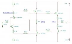
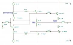
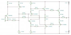
Nothing special , just the luxman/ hawksford voltage stage with a standard Vbe.
(Below) is what I ran for 8 months a year ago and have been running for the last 3 weeks. It references to page 144 - fig. 7.14 in the book , is similar to the Holman apt1 , but has the hawksford VAS.
R7 (ccs adjust) - you can set IPS/VAS currents , by trimming R21 - offset can be adjusted. Super simple - I have tried CFP inputs , but not the FET/cascode arrangement.
Would most likely be a very nice amp on a standard Lateral OPS - with drivers.
THD20 is stellar - can match or beat a TMC LIN with twice the loop gain(below2). EF2 gets a "whoopin'" at 2 and 4 R , as well (THD wise)
No "secrets" around here
.OS
Attachments
Tekko,
Unfortunately, yes, that in post #2050 more quickly. It´s a pity since it has advantages over the Vbe multiplier.it will go into thermal runaway
Tekko,
Unfortunately, yes, that in post #2050 more quickly. It´s a pity since it has advantages over the Vbe multiplier.
Hi WuYit,
Could you elaborate on what you consider the advantages over the Vbe multiplier are?
Cheers,
Bob
Bob,
I see the Vbe multiplier as a disturbance in the VAS load (a nonlinear element). In this way, no need for an in itself aggravating bypass capacitor to improve high frequency distortion and transient response.
Another problem with the triple (when composed of devices with the same polarity) is an alarming rise in saturation voltage.
Attachments
Last edited:
- Home
- Amplifiers
- Solid State
- Bob Cordell's Power amplifier book