most of what you need to measure are low Z nodes, could use optoisolator to get < a few pF to VAS for bias spreader control
whole circuit bootstrapped from the output, could add only few 10s of pF on the output even with small line xfmr
Bob's EC circuitry can be seen as an example of bootstrapped circuitry
I like analog design, but at some point just wanting a result leads me to using today's Big Stick - cheap uC, ADC/DAC, some software
What make you think opto does not have drift problem with temperature?
It's not the stuffs hanging on the output transistors that I worry, it's the circuit hanging on the VAS I worry about.
You want to power the circuit floating on VAS, you need to have the power supplies floating on the VAS. With every power supply, there will be a transformer coupling to the primary that connect to the power source. You going to use DC to DC converter? Then you have switching problem. You use regular supply, then you are going to hang long wires to the supplies.
It's not the idea of the circuit, of cause it works, it's more precise and cheap. It's the implementation that's the problem. It's like hanging a big antenna on the VAS, capacitor shunting to ground, worst to the AC source.
How much pcb space you are willing increase to put all these in? It's not just the uC, I know, you can buy a uP with ACD, DAC and all, I designed plenty at work. But how about the supplies, filters of supplies, all the opamps, wiring and lots of space on pcb that you have to pay. The uP is the smallest of the cost.
Last but not least, how much harder do you think it would be to layout that pcb to take care......say mitigate the issues I outline above?
To me, the first and foremost is the layout. Layout makes or breaks the project. Less is more when comes to layout. I am sure I can beat the problem by just hand pick transistors. I wrote the long justification on hand picking twice and I don't want to repeat again.
EDIT:
Even if you use DC/DC converter to save space and think that the switching frequency is way beyond the audio range. You still have to worry about two of these with similar frequency and harmonics and mix down to audio frequency. There are f1-f2 components that create IM down to very low frequency.
Last edited:
I suggest you just chill on the laundry list objections - I am a 3 decade experienced designer of scientific and industrial instrumentation electronics - some with isolation, using a variety of strategies
if you have an interest and a focused question fine, if you're not interested that's fine too
but telling the more experienced how things can't work is not the quickest way to learn
if you have an interest and a focused question fine, if you're not interested that's fine too
but telling the more experienced how things can't work is not the quickest way to learn
Don't make it personal, stay with the circuit.I suggest you just chill on the laundry list objections - I am a 3 decade experienced designer of scientific and industrial instrumentation electronics - some with isolation, using a variety of strategies
if you have an interest and a focused question fine, if you're not interested that's fine too
but telling the more experienced how things can't work is not the quickest way to learn
I have 3 decades of working experience working for LeCroy designing transient recorders(digital scope), IC design Exar, Ultra Sound medical imagining for Siemens and Designing all sort of Mass Spectrometers use in Semi Conductor industry for Charles Evans and Assoc., Physical Eletronics and Revera. I still contracted with Revera to research on reading down to 5pA to 0.1% precision in less than 3uS and Channeltron pulse counting to way over 10M counts per second. I was the first to design a 50pS resolution TDC with 25nS dead time and constant fraction module that have less than 10nS dead time in the 90s. If you work on scientific instruments, you should know what I am talking about.
I did plenty of isolation switching HV supplies with precision control floating on 10KV+ using opto coupling control. I designed using uP with ADC and DAC floating on 10+KV. Those floating supplies are all controlled by uP floating on different voltage. I designed with HC11 and ADuC831 for micro controllers for many projects until I retired 10 years ago. Revera still called me back to do the research after 10 years of retirement, paying me to work at home!!! I know plenty of floating and the catch of doing that.
So when I wrote that, it's from 30 years of experience even though I am new in audiophile. You can put me down on audiophile, but not in general electronics.
Last edited:
I have 3 decades of working experience working for LeCroy designing transient recorders(digital scope), IC design Exar, Ultra Sound medical imagining for Siemens and Designing all sort of Mass Spectrometers use in Semi Conductor industry for Charles Evans and Assoc., Physical Eletronics and Revera. I still contracted with Revera to research on reading down to 5pA to 0.1% precision in less than 3uS and Channeltron pulse counting to way over 10M counts per second. I was the first to design a 50pS resolution TDC with 25nS dead time and constant fraction module that have less than 10nS dead time in the 90s. If you work on scientific instruments, you should know what I am talking about.
I did plenty of isolation switching HV supplies with precision control floating on 10KV+ using opto coupling control. I designed using uP with ADC and DAC floating on 10+KV. Those floating supplies are all controlled by uP floating on different voltage. I designed with HC11 and ADuC831 for micro controllers for many projects until I retired 10 years ago. Revera still called me back to do the research after 10 years of retirement, paying me to work at home!!! I know plenty of floating and the catch of doing that.
So when I wrote that, it's from 30 years of experience even though I am new in audiophile. You can put me down on audiophile, but not in general electronics.
Wow, though:
I never have a degree in EE
You must be the smartest self-educated man since Edison.
Know that all the "audio" stuff that you are so concerned about (Oliver bias, class A, thermal budgets, diode nonlinear capacity, long tail diff pair balancing, current feedback, etc... all fully understood since the early 70's) are undergraduate topics in any decent EE program. How you were able to design linear IC's at Exar without this elementary knowledge is one of those deep mysteries. Are you sure you weren't at the time into Rubilith cutting and peeling?
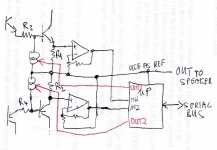
Lets forget the personal stuff. I actually was thinking how to not touching the VAS and still using uP for control. Attached is my thinking. As you can see, I totally leave VAS alone as long as it's set to reasonable bias. It does not even have to be on the heatsink as drift is no longer important.
If you look at the circuit. I use the output of the amp as reference ground for the uP circuit. You can hang stuffs on the output and it does not care. I use the muxed ADC input of the uP to read the voltage across R1 and R2 which is the Re of the transistor to read the current. Then I control the voltage across the R1 and R2 by sourcing and drawing current through R3 and R4 to change the voltage across R1 and R2 respectively. With this, I can precisely control the voltage ( say current ) across the Re and hence through the transistor. This will totally eliminate current hogging. You can do the closed loop stability poles and zeros in the firmware.
I still don't condone this as it's still a lot of circuits. But just to think out loud.
Attachments
Last edited:
Wow, though:
You must be the smartest self-educated man since Edison.
Know that all the "audio" stuff that you are so concerned about (Oliver bias, class A, thermal budgets, diode nonlinear capacity, long tail diff pair balancing, current feedback, etc... all fully understood since the early 70's) are undergraduate topics in any decent EE program. How you were able to design linear IC's at Exar without this elementary knowledge is one of those deep mysteries. Are you sure you weren't at the time into Rubilith cutting and peeling?
I studied hard!!! even I work 40 hours week, I spent all nights and weekends studying. Electronics is my one true passion, I gave up music to pursue electronics.
Yes, I am a total self studier, I got a BSEE in biochemistry only. It is my passion and hobby of my life. I spent the last 7 years after retirement studying 3 hours a day, 5 to 6 days a week, studying EM, RF, differential equation, PDE and all.
You don't need education to be creative, you need education to proof the idea of the creation. I published 2 papers in America Institution of Physics, Review of Scientific Instruments. I own two patents totally under my name and I just got the last one last year on noise cancelling for single coil guitar pickup, and that I wrote my own patent and submitted on my own.
I spent a year designing two guitar amps with power scaling and I just dropped it after they are successful. Now I work on audiophile. I have no plan to stay in this for extend period. I'll jump to other fields after this. This is an adventure for me. Just like in my career, I don't repeat experience until I got older. Every company I work for the first 10 years are of totally different from each other, always leaving on top of the game. It's because I designed tube guitar amp already, that's why I pass up the tube audiophile amp and come the SS first. Don't want to stay in the comfort zone.
But can we get back to electronics how?
Last edited:
If you look at the circuit.
You may want to take a second look yourself. The bottom opamp has a negative output, the A/D channel may not like that. My dog could draw such a "schematic", too bad I don't have one.
I did think that the idea of feedback, correction in the digital domain- explicit mention of continuous model identification might kind of cover "What make you think opto does not have drift problem with temperature?"
which I took to be a naive objection by someone not having a clue or giving any thought to my post
I personally would investigate the common emitter/floating supply topology if I felt the need to design a power amp
having designed digital strain gage amps with Av 4000 inputs, 16 bit ADC within inches of 40 MHz DSP, 386 and verified 1 dB noise figure, diagnosed and corrected sub lsb quantization error from inadequate IIR filter accumulators designed by the highly recommend DSP consultant...
last paid project used isolation in a high speed USB update of the earlier strain gage amp with 100 MHz processor in 1/4 of the pcb area...
my credential is actually a Biology degree - but I discovered in my Junior year "24 hour lab" that I wasn't cut out for Science - all of my friends were EE/CS and the "instant feedback" from changing code or component value sure beat waiting for weeks to see if the spots growing in the grids on your petri dish may mean something - a few linear systems and control theory courses later and I "got" electronic design and have earned my living doing it ever since – with lots of continuing self-education along way
Yes, I am a total self studier, I got a BSEE in biochemistry only. It is my passion and hobby of my life. I spent the last 7 years after retirement studying 3 hours a day, 5 to 6 days a week, studying EM, RF, differential equation, PDE and all.
You missed studying coherent sheaves on a Calabi–Yau manifold. Drop electronics and go for it, people at arXiv.org e-Print archive are waiting for your results.
The nonlinear capacitance of your diode is the reason why this type of diode feedback arrangement is not generally used to prevent saturation of the VAS transistor, so it is a concern. I think most amps just let the VAS saturate in clipping. Pick your poison.
BTW, the 2T Darlington VAS brings with it the advantage that the Ccb of the main VAS transistor is not allowed to be fed back to the input of the 2T VAS, so the effect of the nonlinear Ccb of the VAS transistor is nearly eliminated.
Cheers,
Bob
I don't let it saturate. Why would a small non-linear capacitance make a
difference ?
I use BAVxx in just this configuration. One test with/without , amp
still was single digit PPM.
On the simulator , a poor diode (1n4148) also performs poorly ... with
that capacitance.
Neither diode datasheets show any sort of Vr versus capacitance plot.
Models for these diodes show The BAV having little effect and the
4148 degrading performance considerably (LTspice).
Please explain the "all diodes are bad here" statement. I have
not seen this with the low capacitance component ??
OS
I don't let it saturate. Why would a small non-linear capacitance make a difference ?
It's called PIM. Does it really matter for the sound quality? Probably not.
It's called PIM. Does it really matter for the sound quality? Probably not.
PIM- passive intermodulation distortion. Would the diode be passive
in regard to it capacitance ?
"probably not" ... the forums Badger and my sub amp use the diode.
As I said , have not heard or measured much difference.

OS
PIM- passive intermodulation distortion. Would the diode be passive
in regard to it capacitance ?
"probably not" ... the forums Badger and my sub amp use the diode.
As I said , have not heard or measured much difference.
OS
Phase intermodulation. Essentially, modulation of the ULGF by the input signal.
Do it, and Mr. Curl will eat you alive. You know, he did it 40 years ago.
There is a slight problem with your circuit aside from obvious errors that I'm sure you are aware of.If you look at the circuit. ... loads fancy explanation & a circuit ...
I still don't condone this as it's still a lot of circuits. But just to think out loud.
The current in dem resistors will vary from quiescent (which I presume your uP attempts to control) and zillion Amps when you are making a noise.
But seriously ...
I've been looking at analogue means of controlling Iq directly. But whether you do it analogue or digital, its still a control loop and I'm not sure its possible to have it behave like we want to.
Might have to actually burn solder & try it out.
What and who conducted the test? Details please.ostripper said:I use BAVxx in just this configuration. One test with/without , still was single digit PPM.
You easily get around this problem by using the collector/base junction of the generic NPN & PNP in LTspice.
A single pair of these incredible devices can be used for zillion W amps avoiding current hogging and other evils.
Pity both Mouser & Digikey are out of stock
Last edited:
Otala and disciples never seem to credit any but the static nonlinear input stage gm, dominant pole comp analysis "supporting" the "flat loop gain" prescription
of course there are many PIM sources, including semi junction nonlinear C that can have higher dynamic nonlinear consequences and would actually require rising loop gain over audio if they were right
of course there are many PIM sources, including semi junction nonlinear C that can have higher dynamic nonlinear consequences and would actually require rising loop gain over audio if they were right
Last edited:
You may want to take a second look yourself. The bottom opamp has a negative output, the A/D channel may not like that. My dog could draw such a "schematic", too bad I don't have one.
This is only the concept of reading and controlling just on the output transistor side, does not involve the VAS that is much more sensitive.
There are bipolar ADC, if not, you offset to unipolar. With NPN and PNP, you have to do it bipolar.
Don't think this is a working circuit. I am not even condone this, it's just curiosity got the best of me and hurry up draw it out just to talk about it.
AND cut the sarcasm.
Phase intermodulation. Essentially, modulation of the ULGF by the input signal.
Do it, and Mr. Curl will eat you alive. You know, he did it 40 years ago.
Oh , multiple definitions for that acronym
.So a few pf modulation of the 60-70pf TMC value.
I have a lot of PM at my chosen values , should I worry more about
the actual modulation ? .... or just be happy that my saturation is
gone (and it works).
Would not want to (mess with) Mr. Curl. he's the "guru" , I'm just barely
a "pitchfork villager".
OS
my credential is actually a Biology degree - but I discovered in my Junior year "24 hour lab" that I wasn't cut out for Science - all of my friends were EE/CS and the "instant feedback" from changing code or component value sure beat waiting for weeks to see if the spots growing in the grids on your petri dish may mean something - a few linear systems and control theory courses later and I "got" electronic design and have earned my living doing it ever since – with lots of continuing self-education along way
Sounds like your background is kind of similar to me. Mine is biochem. I hated the lab, I cannot imagine staying in the lab smelling all the crap. I started out as pre-med, hated biology and the lab. Moved to Chemistry, still hated the lab. In the 70s, you can't find job in it that easily, I never even sent out a single resume. Been a pizza delivery boy and finally applied to a hand held tape recorder field service job. At the same time, I was very serious in playing music. But slowly, electronics took over. I was so into it that I quit music. I studied so hard and cut corners in the service job that I got fired!!! Instead of being bitter, I stayed home studying 18 hours a day for 3 months and got into the job as a test technician.
Back in the days, digital electronics just got hot, I took one class in heald college in digital electronics for technician, and thanks to a senior engineer that did not know how to design, I got to correct his mistakes and slowly worked my way into assembly language programming. We were working on the fusion project contracted to Lawrence Livermore Lab in 1979. I got to design small circuits and did the programming. That's how I got started. Then actually the senior engineer Jim Cummins that could not design pulled me to LeCroy in 1982 and really started my career.
I have to consider myself very blessed. My job was and is my passion. I would do it all over again if I have to. I talk a lot on the forum because I have no one share my passion, the passion of just designing, learning new electronics. 30 years, still going strong. Still live, breath electronics. While my wife like to cruise, I always take my books to the cruise. while she go walk around, shopping on the deck, I stay in my room and read!!! that's what I like about cruising. I can get more learning on a cruise and come back refreshed.
Ah, I talk too much already.
Last edited:
A .What and who conducted the test? Details please.
B. You easily get around this problem by using the collector/base junction of the generic NPN & PNP in LTspice.
A.link - http://www.diyaudio.com/forums/solid-state/248105-slewmaster-cfa-vs-vfa-rumble-66.html#post3965982
Member 5th element - "wolverine" blameless IPS.
Soundcard - pretty low ppm up to what the limited hardware could
measure. He tried many configurations.
B. You mean use a transistor as diode ?
OS
There is a slight problem with your circuit aside from obvious errors that I'm sure you are aware of.
The current in dem resistors will vary from quiescent (which I presume your uP attempts to control) and zillion Amps when you are making a noise.
But seriously ...
I've been looking at analogue means of controlling Iq directly. But whether you do it analogue or digital, its still a control loop and I'm not sure its possible to have it behave like we want to.
It is a concept, the point is to set the current through the Re and control it to keep it as a set DC level. Then correct the current by changing the voltage across the base stop resistor which directly control the voltage drop across the Re.
Of cause there is a lot more technical details like bipolar or unipolar and you need circuit to accommodate that. I only spent 5 minutes drawing out and post it so people can think about it and talk about it.
You have to also use the program to average out the AC variation of the current during the music is playing as it is likely symmetrical waveform. It's all in the programming.
Bottom line, the concept is reading the voltage across Re, vary the current of the base stop to keep Re in constant bias current to prevent hogging and slow drift during warmup. this avoid touching the sensitive VAS all together. You program the bias current in the uP, not adjust in the spreader. the transistors can in different heatsink and you can still control it precisely.
Last edited:
- Home
- Amplifiers
- Solid State
- Bob Cordell's Power amplifier book