I'm coming a bit late to this party, but I will just remark that I have used Re=0.1 ohm on every amplifier I have designed since 1990. This includes large-scale production (in the tens of thousands) of amplifiers with multiple output stages. There are no problems so long as you give due thought to thermal compensation.
I have not explored lower values, but they do promise less crossover distortion if they can be made safe.
Hi Doug,
Its good to see you back. Perhaps I am being too conservative in advising against 0.1 RE, and there may be particular designs where it is safe in terms of thermal runaway. An example might be output stages using ThermalTrak transistors. But for conventional EF output stages, I still maintain that one cannot make the general statement that 0.1 is safe.
There is no disagreement that lower RE properly biased to the Oliver criteria will in principle result in lower static crossover distortion. The reduced RE allows higher bias current, increasing the size of the class A region and reducing the output impedance of the output stage, and therefore reducing the percentage of output impedance change as a fraction of the load impedance
In my chapter 14.6 I discuss local thermal stability at length, with focus on Fig. 14.15 and Eq. 15.2. I describe local thermal stability as the case where the heat sink is not in the equation - it is considered infinite. I think this is the best you can do in principle with thermal bias stability.
With Eq. 15.2 there is considerable discussion and sanity check examples as described in Eqs 15.3 - 15.6. Can you tell me what it is about the material in chapter 14.6 that you disagree with, particularly Figure 14.15 and Eq. 15.2. If there is an error, or there needs to be some added caveats, or examples of mitigating circumstances, I want to improve the treatment in my second edition.
My focus in Eq. 15.2 is on EF output stages. I also believe that 15.2 applies to both single and multi-pair output stages.
Regarding the amplifiers that you have had experience with using RE = 0.1,
where any of them EF outputs (as opposed to CFP) and did they use base stopper resistors (and if so what value)?
Cheers,
Bob
I'm coming a bit late to this party, but I will just remark that I have used Re=0.1 ohm on every amplifier I have designed since 1990. This includes large-scale production (in the tens of thousands) of amplifiers with multiple output stages. There are no problems so long as you give due thought to thermal compensation.
I have not explored lower values, but they do promise less crossover distortion if they can be made safe.
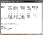
I gave a lot of thoughts with equation 15.2 in page 300 of Mr. Cordell's book. I agreed with the equation. I turn the equation around to find maximum safe rail voltage with the given parameters( realistic thermal resistance from junction to heatsink of the huge TO-264). To calculate the max rail voltage:
For static bias of 216mA and 0.1ohm resistor
1) gm=1/(0.12+0.12)=4.17A/V.
2) Thermal resistance from junction to heat sink = 1.1deg/W for TO-264.
3) TC_Vbe =-2.2mV/deg C.
4) Vrail = 0.5/(4.17A/V X -0.0022V/deg X 1.1deg/W)=49.5V.
The maximum voltage is less than 50V.
So what is the maximum rail voltage you have tried? Do you have theory behind why it is safe to use 0.1ohm or just by pure experimental result?
Hi Alan,
Pull your nose out of the books now and then. I was referring to real music in operation in a household. Now, consider peak to average levels again.
You have to consider how a thing is used to design well. An amplifier for a laboratory has to be designed to deliver its rated power across it's rated bandwidth all day long. In a house, the situation is rather different. The ratio between clipping and the average levels would run from about 10:1 for FM (say), and 15:1 for the average dynamic CD. So knowing this, you can calculate what the average dissipation needs to be (plus the peaks) and design to that. Many commercially produced sound equipment can't even survive those levels.
To be clear, you have to digest what is said in books and apply what you learn to real life. If you are too literal you will never understand what is going on, nor will you be able to make decisions regarding how things should be designed. You only get that spark from building things on your bench and playing with individual components and simple circuits. There is no better teacher to give you the "feel" for what you are doing.
-Chris
I agree that I need to get my hands on the circuit to get the feel. Just I don't have all the parts, still waiting.
Regarding to 0.1ohm or 0.12ohm. If you run 200mA, the static power dissipation is quite prohibited if you have over 40V rails even without using equation 15.2. This is beyond books, just W=IV. To make that happen, you have to buy a $500 chassis with huge heatsink.
I went through a lot of talking, I paid $280 for my chassis, the safe idle dissipation(no music) cannot be over 70W per side. That's the limiting factor. For 5 stages 200mA each, I can't even use 40V rail without pushing over the limit.
3 "Camps"....
1.- Hi- end amps <.1Re with a price sticker to match. Enough "value added"
cash to hire someone in the back room with a curve tracer.
Extra profit by selling said matched as "genuine replacement" devices.
2- Standard Japanese OEM with stock Sanken and the Holy .22R dual
noble resistors.
3- Various amps meant for abuse (musicians) with .33R or above.
Also , some internet designs meant to be forgiving for a first time builder.
Only #1's I've seen (Hi-end) did not use <.1R .... HK990 (2K$) =.22R
Genesis stealth = also .22R . All the schema's that specify .1R also
list the outputs as "special/genuine" at big $$$.
Most reports of catastrophic failure is with this class.
The #2 scenario , I've seen hundreds. Single pairs , two pairs - many pairs.
Very few have output failure unless thermal grease dries out or pennies
drop inside . Output stages still work with leaky supply caps.
Number 3 - I seen some , and they are quite durable . SUNN keyboard
amps with .33R and TO-3 NPN only output stages - last forever , caps
go bad.
I don't think Bob is "being too conservative " - the "survivors" I've seen
that last through electrolytic (replacement) cycles all use the standard .22R .
Some of the best reviewed upper- mid to high end also use this
value.
To recommend a lower value to DIY'ers is (not good advice). They will
not likely have the facilities to build safe projects with that recommendation.
My oldest "blameless" /(Badger) is almost 4 years old , no reports of
smoke.
OS
1.- Hi- end amps <.1Re with a price sticker to match. Enough "value added"
cash to hire someone in the back room with a curve tracer.
Extra profit by selling said matched as "genuine replacement" devices.
2- Standard Japanese OEM with stock Sanken and the Holy .22R dual
noble resistors.
3- Various amps meant for abuse (musicians) with .33R or above.
Also , some internet designs meant to be forgiving for a first time builder.
Only #1's I've seen (Hi-end) did not use <.1R .... HK990 (2K$) =.22R
Genesis stealth = also .22R . All the schema's that specify .1R also
list the outputs as "special/genuine" at big $$$.
Most reports of catastrophic failure is with this class.
The #2 scenario , I've seen hundreds. Single pairs , two pairs - many pairs.
Very few have output failure unless thermal grease dries out or pennies
drop inside
. Output stages still work with leaky supply caps.Number 3 - I seen some , and they are quite durable . SUNN keyboard
amps with .33R and TO-3 NPN only output stages - last forever , caps
go bad.
I don't think Bob is "being too conservative " - the "survivors" I've seen
that last through electrolytic (replacement) cycles all use the standard .22R .
Some of the best reviewed upper- mid to high end also use this
value.
To recommend a lower value to DIY'ers is (not good advice). They will
not likely have the facilities to build safe projects with that recommendation.
My oldest "blameless" /(Badger) is almost 4 years old , no reports of
smoke.
OS
Last edited:
Hello Bob
I think a lot of the fear of thermal runaway dates all the way back to germanium transistors, which were:
1) Much more prone to it.
2) Damned expensive at the time. Runaway was quite a disaster.
The various designs were about 50:50 EF vs CFP. depending on the exact requirements, both single & multiple outputs. I have never (so far) used so called base-stopper resistors because they make linearity into sub-8R loads much worse. I assume you are aware of this.
Well, I think I have shown that one certainly can, with the proviso that there is effective thermal compensation and adequate heatsinking. I have only once ever seen thermal runaway occur in my life- in an amplifier I was asked to evaluate. The 'designer' decided that the flat steel underside of the case would be enough heatsinking, and there was the added feature of black crackle paint between the transistors and the plate. I had it idling for about 20 minutes before Prompt Disassembly occurred.Hi Doug,
Its good to see you back. Perhaps I am being too conservative in advising against 0.1 RE, and there may be particular designs where it is safe in terms of thermal runaway. An example might be output stages using ThermalTrak transistors. But for conventional EF output stages, I still maintain that one cannot make the general statement that 0.1 is safe.
I think a lot of the fear of thermal runaway dates all the way back to germanium transistors, which were:
1) Much more prone to it.
2) Damned expensive at the time. Runaway was quite a disaster.
I'l have to get back to you when I have time to look at these references. Very busy with client meetings at present.In my chapter 14.6 I discuss local thermal stability at length, with focus on Fig. 14.15 and Eq. 15.2. I describe local thermal stability as the case where the heat sink is not in the equation - it is considered infinite. I think this is the best you can do in principle with thermal bias stability.
With Eq. 15.2 there is considerable discussion and sanity check examples as described in Eqs 15.3 - 15.6. Can you tell me what it is about the material in chapter 14.6 that you disagree with, particularly Figure 14.15 and Eq. 15.2. If there is an error, or there needs to be some added caveats, or examples of mitigating circumstances, I want to improve the treatment in my second edition.
My focus in Eq. 15.2 is on EF output stages. I also believe that 15.2 applies to both single and multi-pair output stages.
Regarding the amplifiers that you have had experience with using RE = 0.1,
where any of them EF outputs (as opposed to CFP) and did they use base stopper resistors (and if so what value)?
Cheers,
Bob
The various designs were about 50:50 EF vs CFP. depending on the exact requirements, both single & multiple outputs. I have never (so far) used so called base-stopper resistors because they make linearity into sub-8R loads much worse. I assume you are aware of this.
Hey Doug!
Good to see you on here.
You can use 0.05 ohm resistors as you have opined. Carver built many products using that value with no ill effects.
-Chris
Thank you! Would be here more if I had the time.
You are quite right- Carver used 0R05 in the M1.0t power cube, for one example. But everything I have heard indicates that Carver's designs were not exactly noted for reliability
Technical Brain does away with external Re.
Looks to me as though it would do away with a lot of power transistors too.
I would never do anyting like that around the OPS, but that doesn't mean that there's nothing else to learn from. The best output amplifier we have ever used on a show is an Adyton from Norway. That uses 0,68 ohm and 7 pair BJT per channel. Somehow I fail to see how lower Re means better sound quality. I would much rather look at how to maker turn off/on softer.
Simulation vs. "real world" ....
Back a hundred posts , there was doubt as to the accuracy of a simulated amp.
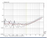
(below 1) is the 1K thd simulated. (below 2) is a sound card test.
The limited sample rate of the PC's ADC (should ) not give reliable
>10Khz results. The simulator tells me I should have <20ppm , even at
20K and a much higher power.
I'm sure an AP would show much better >10K.
So , the sound card is mediocre. The blameless test I mentioned at 5ppm/20K
was a VERY expensive setup. Most likely still short of an AP.
The 1K test tells me a lot. If 3-4ppm is exactly the output
from the real amp (and simulator) at 1K with a given set of models , so should it be
at 20K.
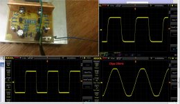
(Below 3) the scope tests also coincide with the simulator. If 100K
is that smooth , I'm sure a measured AP would possibly be better
than the simulation >10K .
BTW - this is 10 device symmetric "abomination" .... NO "can of worms"
or any other "errata" . In fact , would most likely be more robust in
an abusive environment.
Full test is here - http://www.diyaudio.com/forums/solid-state/248105-slewmaster-cfa-vs-vfa-rumble-165.html#post4390928
PS - this is the "entry level" input stage. was not designed to be a ultra
low THD-20k input stage.
OS
Back a hundred posts , there was doubt as to the accuracy of a simulated amp.
(below 1) is the 1K thd simulated. (below 2) is a sound card test.
The limited sample rate of the PC's ADC (should ) not give reliable
>10Khz results. The simulator tells me I should have <20ppm , even at
20K and a much higher power.
I'm sure an AP would show much better >10K.
So , the sound card is mediocre. The blameless test I mentioned at 5ppm/20K
was a VERY expensive setup. Most likely still short of an AP.
The 1K test tells me a lot. If 3-4ppm is exactly the output
from the real amp (and simulator) at 1K with a given set of models , so should it be
at 20K.
(Below 3) the scope tests also coincide with the simulator. If 100K
is that smooth , I'm sure a measured AP would possibly be better
than the simulation >10K .
BTW - this is 10 device symmetric "abomination" .... NO "can of worms"
or any other "errata" . In fact , would most likely be more robust in
an abusive environment.
Full test is here - http://www.diyaudio.com/forums/solid-state/248105-slewmaster-cfa-vs-vfa-rumble-165.html#post4390928
PS - this is the "entry level" input stage. was not designed to be a ultra
low THD-20k input stage.
OS
Attachments
Last edited:
for one example.
Stacked by another power device, and power resistor.
As the Silver 7T, as the Silver 9T.
Afair, Mr Carver used common emitter resistor values in his more common transistor PP output stages, as high as 0R33
Hello Bob
Well, I think I have shown that one certainly can, with the proviso that there is effective thermal compensation and adequate heatsinking. I have only once ever seen thermal runaway occur in my life- in an amplifier I was asked to evaluate. The 'designer' decided that the flat steel underside of the case would be enough heatsinking, and there was the added feature of black crackle paint between the transistors and the plate. I had it idling for about 20 minutes before Prompt Disassembly occurred.
I think a lot of the fear of thermal runaway dates all the way back to germanium transistors, which were:
1) Much more prone to it.
2) Damned expensive at the time. Runaway was quite a disaster.
I'l have to get back to you when I have time to look at these references. Very busy with client meetings at present.
The various designs were about 50:50 EF vs CFP. depending on the exact requirements, both single & multiple outputs. I have never (so far) used so called base-stopper resistors because they make linearity into sub-8R loads much worse. I assume you are aware of this.
Hi Doug,
Do you not use base stopper resistors on your designs with multiple output pairs?
If not, I am not aware of any alternate ways of ensuring HF stability among multiple output pairs in your book. Do you do anything special to allow you to get away without stoppers, or do you believe that the use of stoppers is not generally needed anyway?
Many, many designers would love to hear that stoppers are not necessary, not the least of whom would be John Curl and myself.
Cheers,
Bob
Hello Bob
I think a lot of the fear of thermal runaway dates all the way back to germanium transistors, which were:
1) Much more prone to it.
2) Damned expensive at the time. Runaway was quite a disaster.
The various designs were about 50:50 EF vs CFP. depending on the exact requirements, both single & multiple outputs. I have never (so far) used so called base-stopper resistors because they make linearity into sub-8R loads much worse. I assume you are aware of this.
Isn't it dangerous if you don't use base stop resistor for multiple pair of EF in parallel? It is well known this can cause oscillation due to cross talk between power transistor and having a resistor at the base of each transistor tame the oscillation. This is not just in audio power amp, this is very standard whenever you parallel devices together. The higher the frequency, the more critical it is. I design RF, I would never think of not having a base stop resistor or ferrite bead on the base if I parallel devices.
Regarding to 0.1ohm resistor and base stop, do you hand pick matching transistors. I am sure it is safe if you match beta and Vbe.
Do you have analytical theory behind this or just from building many amps?
Last edited:
Isn't it dangerous if you don't use base stop resistor for multiple pair of EF in parallel? It is well known this can cause oscillation due to cross talk between power transistor and having a resistor at the base of each transistor tame the oscillation. This is not just in audio power amp, this is very standard whenever you parallel devices together. The higher the frequency, the more critical it is. I design RF, I would never think of not having a base stop resistor or ferrite bead on the base if I parallel devices.
I believe it also helps to prevent “parasitic” oscillation of the output stage by making the load on the preceding driver stage look more resistive. EFs can go unstable if their load is too reactive at high frequency. Base stoppers therefore can be needed even if there’s no paralleled devices.
My experience with ferrite beats are for higher frequency, I am not even sure ferrite beats work down to below 50MHz that well where that's what the big transistor with fT< 50MHz need. It's like a single turn inductor. I'll stay with resistor.
Designing a circuit to function the way you want is one thing, make it not oscillate is just as if not more important as once it oscillate, all your good work and creativity gone down the toilet.
There might be some high end amps that use 0.1 and no base stop. BUT there there are enough high end amp like Threshold, Pass Lab and even Accuphase that use larger Re and base stop. Don't tell me Threshold and Pass Lab are not at the tip top of the game. I don't exactly put these in the same category with Sansui, Pioneer, Cambridge and even Carver.
I further looked at schematic of Krell, Bryston, Aragon, Leach. Some don't use base stop, but ALL use Re. Everyone use larger than 0.15....more like 0.22. don't tell me these are not high end.
Sorry.
Last edited:
you can get enough Z at 10 MHz - 0.3 Ohm DC, >200 Ohm |Z| @10-300 MHz for the 1st 1206 part I just looked up
may want to parallel with a R to control the peak Z
Ferrite beads seem attractive in that they avoid exacerbating current hogging issues like base stop resistors do. However they are horribly non-linear (start to saturate at pretty low currents relative to their headline ratings) and it feels wrong to be putting such a thing into a circuit we are trying desperately to linearise. That being said the non-linearity should be well above audio frequencies and I have never done or seen any distortion measurements for an output stage with/without ferrite beads.
It’s also possible that the saturation issue might mean that things look good with small output signals, but the high-frequency base-stop resistance being provided by the ferrite bead will reduce with transient signal peaks, possibly to an extent that those HF nasties may appear.
I don't think you need to worry about non linear of ferrite beads. They operates in much higher than audio frequency. I don't think it's that easy to saturate a one turn inductor which the beads are. My concern is they are not very good at audio frequency device.
Just as a random example, see this data sheet for some 1 A and 3 A rated ferrites. Look at figures xxB on the second page to see how the impedance varies with DC bias current.
http://www.farnell.com/datasheets/327249.pdf
Ferrite has a low saturation flux density of typically 300 mT or less. Coupled with high µr, it is easy to saturate.
- Home
- Amplifiers
- Solid State
- Bob Cordell's Power amplifier book