Originally Posted by Alan0354
I thought about that also
Prove it ! Only kidding
")
Ahh well, just an idea
Hi Alan,
Just to rock the boat with a fact. Many Carver power amplifiers used 0.1 and 0.05 ohm emitter resistors ... with 125 VDC rails. That's 250 VDC across the driver stage.
Okay, I cheated you. The primary supply the Carvers run off is about 25 to 30 VDC, then a second tier supply and finally the 125 V rails. But, those drivers see the full rail voltage all the time. During music peaks those amplifiers hang together just fine, but if a rail locks up the amp will go into thermal runaway (it will shut down though, not go bang).
My point here is that you can't settle in for absolute rules. There is always give, and you can easily use very low emitter resistance as long as you design for it. Also, I am not advocating anyone use Bob Carver's approach. It works for him.
When you clued into beta being the important factor in current sharing - you hit the nail on the head. As the current goes up, the voltage across the emitter resistors completely swamp out a few mV difference between output E-B voltages. It's the beta that causes current hogging and the extra heat just exacerbates the situation. Heck, differences between the resistances in emitter resistors will swamp out the Vbe differences - within reason!
-Chris
Hi Alan,
Just to rock the boat with a fact. Many Carver power amplifiers used 0.1 and 0.05 ohm emitter resistors ... with 125 VDC rails. That's 250 VDC across the driver stage.
Okay, I cheated you. The primary supply the Carvers run off is about 25 to 30 VDC, then a second tier supply and finally the 125 V rails. But, those drivers see the full rail voltage all the time. During music peaks those amplifiers hang together just fine, but if a rail locks up the amp will go into thermal runaway (it will shut down though, not go bang).
My point here is that you can't settle in for absolute rules. There is always give, and you can easily use very low emitter resistance as long as you design for it. Also, I am not advocating anyone use Bob Carver's approach. It works for him.
When you clued into beta being the important factor in current sharing - you hit the nail on the head. As the current goes up, the voltage across the emitter resistors completely swamp out a few mV difference between output E-B voltages. It's the beta that causes current hogging and the extra heat just exacerbates the situation. Heck, differences between the resistances in emitter resistors will swamp out the Vbe differences - within reason!
-Chris
Ever had to fix a cube?
Prove it ! Only kidding
Ahh well, just an idea
Actually that's really the first thing comes to mind!!!. It's a good idea if you can find say 2.0, 2.1, 2.2, 2.3, 2.4ohm etc. I was thinking about it but where am I going to find assortment of resistors. You have to cover 20% variations, It's going to be a little hard to hope 5% resistor to give you that.
I gave that up after I measure all the transistors. Particular I can even group the PNP and get sets of 5 with matching beta to 1% or 2% absolute max....Just have to waste 4 of the low beta ones.
Hi Alan,
Just to rock the boat with a fact. Many Carver power amplifiers used 0.1 and 0.05 ohm emitter resistors ... with 125 VDC rails. That's 250 VDC across the driver stage.
Okay, I cheated you. The primary supply the Carvers run off is about 25 to 30 VDC, then a second tier supply and finally the 125 V rails. But, those drivers see the full rail voltage all the time. During music peaks those amplifiers hang together just fine, but if a rail locks up the amp will go into thermal runaway (it will shut down though, not go bang).
My point here is that you can't settle in for absolute rules. There is always give, and you can easily use very low emitter resistance as long as you design for it. Also, I am not advocating anyone use Bob Carver's approach. It works for him.
When you clued into beta being the important factor in current sharing - you hit the nail on the head. As the current goes up, the voltage across the emitter resistors completely swamp out a few mV difference between output E-B voltages. It's the beta that causes current hogging and the extra heat just exacerbates the situation. Heck, differences between the resistances in emitter resistors will swamp out the Vbe differences - within reason!
-Chris
I believe that you can make it work with 0.1ohm like Carver. For one, I really think I was off by factor of 2. The transistor is on about 50% in class AB only, my calculations are assuming 100% conduction that r'e=0. I don't think the real safe operating rail is double the numbers I gave, but I think it's going to be higher. I'll let Mr. Cordell to comment on this.
I want to actually see what beta variation in real device, so last night I measure the beta of over 50 each of the MJW3281/1302 that I bought in 3 different times and from two different places. The NPN is very close, easily find a set of 5 that beta match to 1%. PNP is a little wild, but I can still pick quite a few sets of 5 out of the 50. The process including making the test jig is 2 hours. But once I get into the rhythm, I can crank out really fast.
I can imagine high end amp company can afford to test, label and pick one year of production needs in a day!!!. If I pick matching set to 1% beta and less than 1mV variation of Vbe at a given current, I am sure I can make 0.1 or even lower work.
That's the reason I am doing a lot of talking and use the time of waiting for the 0.22ohm to arrive to think it out loud.
We are here because we all want to make an amp that is better than you can buy regardless of money, I totally willing to hand pick parts and I think people here should consider that too. It is a lot easier than talking about it. ALSO more important, if you plan to make a few amps using the same transistors, you buy 50, I can only see I wasted 4 of the PNP. But if I buy another badge, if I can just find one more, I won't even waste these 4. You are not wasting money buying more as you can find different matched sets out of it. I manage to use them all except the 4....for now, until I buy another badge.
Last edited:
Hi Alan,
Think average to peak power ratios. There is the answer to your other question.
I always buy more parts than I need. You should consider buying one of those assortments of resistors in 1/2W. That should be 169 values. 10 pcs per value would be just reasonable. This will set you up with most of the values you will need. You still have to buy 1 watt and higher resistors as you need them.
-Chris
We are talking about this as if lower Re means better SQ, but is that really the case..?? What about making output impedance different. PASS seems to like some kind of output resistance, or what about a slightly negative output impedance.?? My gut feel says that a slghtly negative output impedance will be beneficial in dealing with real life loads.
We are talking about this as if lower Re means better SQ, but is that really the case..?? What about making output impedance different. PASS seems to like some kind of output resistance, or what about a slightly negative output impedance.?? My gut feel says that a slghtly negative output impedance will be beneficial in dealing with real life loads.
I do notice Pass use higher value Re. Can't argue with Pass. How do you make the output impedance negative?
I am not trying to make it low output impedance, I just try to have a bigger Class A region and satisfy the Oliver's condition. I don't want to have gm doubling by using high current and high Re.
As for sound, I absolutely have no idea. I yet to have my first amp up and running. I just read the books and follow the theory. Still waiting for parts, still busy building the pre amp. I don't have anything set up, everything has to be built. Still deciding whether I want to buy the quantAsylum QA400 THD analyzer....AKA spectrum analyzer. It's a lot of work gearing up for this. All I have spare is a pair of mid line Kef and a pair of bookshelves Monitor Audio for testing.
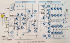
Technical Brain does away with external Re. In many ways this is one brilliant circuit. These amplifiers are sounding good too. Have spent some time with them. A very positive expirence Ii really like the way he balances the output stage and how he makes the feedback.
Attachments
Technical Brain does away with external Re. In many ways this is one brilliant circuit. These amplifiers are sounding good too. Have spent some time with them. A very positive expirence Ii really like the way he balances the output stage and how he makes the feedback.
I looked at it for a few minutes, I don't know it deep enough whether it's brilliant, but it's sure different. It use true differential drive that literally using +/-36V rails to drive as if it's +/-72V rail by using two push pull amps.
Also, it cleaverly limit the push pull VAS current when using complementary IPS. This has been a problem with complementary OPS using CCS load as discussed in this thread before.
The drivers are push pull too.
Hi Alan,
Think average to peak power ratios. There is the answer to your other question.
-Chris
I was thinking about this, I don't think this is necessary true. If you look at the terms of equation 15.2 in page 300, none of the 4 terms has power in them. There is no information of output voltage either only current that affecting r'e. It really just depends of the rail voltage and gm(1/[r'e+Re]). The other two terms, one is physics of tempco of Vbe is -2.2mV/deg C. the other is the thermal resistance from junction to heatsink. These two terms are constant with the later governed by the heatsink and insulation and transistor package.
With the given rail, gm is the only variable. Re is constant, so r'e is really the ONLY one we are talking about.
when I did my calculation, I assume during high level signal where output sink or source a few amps, r'e=0. Again, there is no output power and voltage information. You really have to treat r'e as function of the input signal to calculation the stability under signal.
I am hoping Mr. Cordell can jump in.
you can easily use very low emitter resistance as long as you design for it.
Early series Parasound JC1 had 0R1 emitter resistors.
You'll notice 0R15 specimens if you google JC1 output stage images, mind the odd color coding.
(Mr Curl confirmed the switch to a higher value a number of years ago)
Early series Parasound JC1 had 0R1 emitter resistors.
You'll notice 0R15 specimens if you google JC1 output stage images, mind the odd color coding.
(Mr Curl confirmed the switch to a higher value a number of years ago)
Yes, this is exactly right. The value of the base stopper resistors plays an important role here. Larger base stopper resistance exacerbates the current hogging problem among multiple pairs, even when their betas are reasonably matched. If betas are not matched or poorly matched, large RB can really create a current-hogging problem.
Cheers,
Bob
Hi Bob,
... and so dies the idea of current drive for the output transistors!
I agree.
Hi MiiB,
That is an interesting diagram, any idea of brand or designer? I have been working with very similar output stages myself, but not balanced out (which I don't care for). Everything done looks like it came from an audio design web site - in a good way.
-Chris
Hi
I hate to beat the dead horse over lowering the emitter resistor Re for output EF stage and increase bias current to satisfy Oliver's condition.
If you look at D Self's book p249 Fig 9.19. It is a 3 output stages in parallel. The Re=0.1 ohm that Self has been talking in p279. This is his Class B which is Oliver's condition. He uses 215mA bias current as described in Table 10.2 in p279. He obviously they it's safe to use as low as 0.1ohm Re and not worry about burning the amp!!!
I was told 0.1ohm only works for single output stage, that current hogging can occur when I have multiple output stages in parallel and risk burning the transistor. But Self did it and published in his book. Now I don't know what to think.
I'm coming a bit late to this party, but I will just remark that I have used Re=0.1 ohm on every amplifier I have designed since 1990. This includes large-scale production (in the tens of thousands) of amplifiers with multiple output stages. There are no problems so long as you give due thought to thermal compensation.
I have not explored lower values, but they do promise less crossover distortion if they can be made safe.
Hi Bob,
... and so dies the idea of current drive for the output transistors!
With thunderous applause.
Hi Alan,
Pull your nose out of the books now and then. I was referring to real music in operation in a household. Now, consider peak to average levels again.
You have to consider how a thing is used to design well. An amplifier for a laboratory has to be designed to deliver its rated power across it's rated bandwidth all day long. In a house, the situation is rather different. The ratio between clipping and the average levels would run from about 10:1 for FM (say), and 15:1 for the average dynamic CD. So knowing this, you can calculate what the average dissipation needs to be (plus the peaks) and design to that. Many commercially produced sound equipment can't even survive those levels.
To be clear, you have to digest what is said in books and apply what you learn to real life. If you are too literal you will never understand what is going on, nor will you be able to make decisions regarding how things should be designed. You only get that spark from building things on your bench and playing with individual components and simple circuits. There is no better teacher to give you the "feel" for what you are doing.
-Chris
Hey Doug!
Good to see you on here.
You can use 0.05 ohm resistors as you have opined. Carver built many products using that value with no ill effects.
-Chris
I think JC did one once with no resistors. Was mentioned in the BT thread.
Anatech
The schematic is technical brain, a Japanese high end brand. I find the schematic interesting because of the 2xShunt feedback, dual servos, and the way the way the balanced signal is assembled and then split into a floating push-pull
The schematic is just conceptual as the current sources are not complete, but a lot can be learned from look at how creative and elegant this is done
- Home
- Amplifiers
- Solid State
- Bob Cordell's Power amplifier book