Excuse my ignorance, but in a balanced amp like this how do you ensure that the two halves have similar time delays, given that NPN and PNP are rarely really complementary at higher frequencies? Doesn't this mean that stability is always going to be a problem?
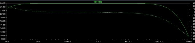
The open loop plot shows a turnover at about 10kHz. What is doing this? I can't see a Cdom capacitor in the circuit.
The open loop plot shows a turnover at about 10kHz. What is doing this? I can't see a Cdom capacitor in the circuit.
Should I fix it? (I already did.) I did not show my final as I would not want to infringe on chinese engineering skills or be responsible for 
 .
.
OS
.NFB and a proper implementation of Cdom (look at the leach amp) will make for a very stable amp , all freqeuncies.Excuse my ignorance, but in a balanced amp like this how do you ensure that the two halves have similar time delays, given that NPN and PNP are rarely really complementary at higher frequencies? Doesn't this mean that stability is always going to be a problem?
OS
All fixed ... Nice amp , very fast. They were just sloppy to get it to market.
Everything was done at 60-0-60VDC , same as leach.
If any want to play.. ebaypooge.zip is the file.
OS
Everything was done at 60-0-60VDC , same as leach.
If any want to play.. ebaypooge.zip is the file.
OS
Attachments
Thank you ostripper!
Thank you for your work, ostripper! You are very kind!
I see I can't use the ebay boards... Too many changes... The input stage, is it possible to make it more like the original circuit? I'm sorry for my ignorance... I know, this is a very noob question. I just wanted to use the pcbs I bought - they are blue and very nice looking and would save me some work.
I'm going to try and simulate the circuit. What is the software you use? I don't have much experience in simulations... I'm a complete noob as you can see. I used before PSpice Student. I'm guessing it's not advanced enough for this. Were do you get the packages for simulation?
Thank you again, ostripper, for your kind work. And thank you all for replying to this thread.
Regards,
Paulo.
Thank you for your work, ostripper!
You are very kind! I see I can't use the ebay boards... Too many changes... The input stage, is it possible to make it more like the original circuit? I'm sorry for my ignorance... I know, this is a very noob question. I just wanted to use the pcbs I bought - they are blue and very nice looking and would save me some work.
I'm going to try and simulate the circuit. What is the software you use? I don't have much experience in simulations... I'm a complete noob as you can see. I used before PSpice Student. I'm guessing it's not advanced enough for this. Were do you get the packages for simulation?
Thank you again, ostripper, for your kind work. And thank you all for replying to this thread.
Regards,
Paulo.
Leave the jumper off unless you are using a DC servo.
POOGE stands for progressive optimization of generic equipment. The Pooge-2 project in the Audio Amateur magazine was on a Hafler DH-200 (which is what yours looks like with the FETs).
I would probably have chosen 4.7 ohms and 0.22 ohms, but your values will probably be OK.
Consider running the drivers a bit harder by changing R29 to 62 ohms, also consider adding a 0.47µF~1µF cap in parallel.
Consider reducing the open loop gain by increasing the values of R4, 5, 8, 9 to as much as 300 ohms (this may smooth out the highs).
Add a high frequency load to the output of the amplifier, 0.1F + 10 ohms is typical. Without this the amplifier could oscillate (and sound like an electric shaver).
Make sure C1 is audio quality (no ceramics please).
Last edited:
With the changes you propose the amp will work fine without oscilating? I don't ear an electric shaver like sound but I'm worried about eventual oscilations outside the audio band that I can'tt ear. Your changes are nice because your way I can use the pcbs.
Thank you, djk
Thank you, djk
Last edited:
I'm using a zobel made with 100nF capacitor and 10 Ohm resistor. No coil. Should I made one? How big (turns and section area)?
I changed the values of R4, 5, 8, 9 to 300 Ohms and the highs became muded. Put back the original values.
I changed then R29 to 62 ohms with a 470nF film capacitor across - as you sugested - and what a difference!
The treble is now very sweet, no harshness at all!
Also checked for oscilations with a receiver as you said, and I picked a noise near 530 kHz (begining of the AM band) but that noise becomes stronger near the transformer and capacitor bank. This is only transformer noise, right? I also checked FM band and couldn't find any noises, unless it was under the imense number of radio stations.
The amp is now sounding very good and working with the 2SJ201/2sK1530 mosfets. Bass is deep, midrange is sweet and treble is just right!
I noticed the driver transistors get very hot... What do you say about increasing R29 a little? What would be the best value?
About the source and gate stopper resistors: I'm using 0.1 Ohm and 10 Ohms. Should I put back the original values of 0.47 Ohm and 221 Ohms?
And that thing about fase response, should I consider more changes like the ones posted before?
My many thanks for your help, djk!
Last edited:
Good to see the results are better, if the drivers are getting too hot theres no problem with increasing the value of resistors a little to reduce the current, maybe do it in small increments until the sound starts to going off. Having the bias current of the drivers increased sometimes helps to stem oscilation if present.
What is the gate resistors codes you refer to ?? Im not sure if youre talking about the gate resistors or the source resistors.
What is the gate resistors codes you refer to ?? Im not sure if youre talking about the gate resistors or the source resistors.
You could experiment changing the value of R29.
The value I suggested is based on using BJT, it could be higher for the FETs. The idea is to have the driver bias close to class A for the level of drive current the outputs require. How hot is hot? The maximum rated junction temperature of the part is 150°C, it would be best not to run it over 100°C. Running the heatsink for this part at 50°C (barely able to touch it for a second or two) should be safe for a very long time.
"I changed the values of R4, 5, 8, 9 to 300 Ohms and the highs became muded."
Changing these will make the amplifier sound softer, but it probably still measures flat. The change reduces the gain in the diff pairs, and push their transient overload outside of normal signal inputs. If you feel the urge to tinker, you could see how 100 ohms sounds. A Leach sounds very soft compared to most amplifiers, even though it measures flat. It is so clean sounding that a bit of treble boost will bring out the HF detail in recordings without sounding harsh. Use your judgment here.
"About the source and gate stopper resistors: I'm using 0.1 Ohm and 10 Ohms. Should I put back the original values of 0.47 Ohm and 221 Ohms?"
The 0R1 is to balance the current through the outputs. With the FETS this value is so low it probably does nothing (because of the high Rds on of the outputs). If the devices are well matched (check the date code lot numbers) they may not be needed (BJT should always use them). If they are not from the same date code lot, the 0R47 may be a better choice. The 10R on the gates is to stop oscillations, and should probably be increase for safety, 221R sounds about right (for those FETs).
"but that noise becomes stronger near the transformer and capacitor bank. This is only transformer noise, right? I also checked FM band and couldn't find any noises,"
Sounds like noise radiated by power supply wiring. This is generally due to rectified currents induced by the power supply diodes. Faster, soft recovery rectifiers may reduce this. The noises we are looking for are AM in nature, and generally show up below 5Mhz. Try and find an unused (quiet) frequency when testing this way.
The output inductor is mainly to isolate the amplifier from low impedance at high frequencies, such as ES and/or piezo speakers. Many newer amplifiers don't have an output inductor.
Good luck with your project, it sounds like you are getting close to where you want to be.
Last edited:
I'm leaning LTSpice and I'm simulating the amp.
I can't get good results with bjt outputs but with mosfets things get better.
A strange thing I find is that raising R29 to 1k gives me much less THD... When I lower from 221 ohms to 68 ohms the sound become better. Isn't this strange? Should I lower or raise R29?
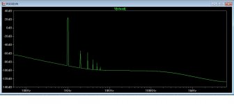
Anyway, the 3rd harmonic is a bit high. Any sugestions to lower the odd harmonics?
Thank you.
I can't get good results with bjt outputs but with mosfets things get better.
A strange thing I find is that raising R29 to 1k gives me much less THD... When I lower from 221 ohms to 68 ohms the sound become better. Isn't this strange? Should I lower or raise R29?
Anyway, the 3rd harmonic is a bit high. Any sugestions to lower the odd harmonics?
Thank you.
Attachments
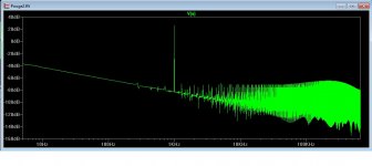
Can you zip the .asc file from your ltspice sim and post it, the result in the pic doesnt look good at all, shows a lot of oscilation.
The value of r30 r31 at 221ohms is fine, for r32 and r33 use a slighly lower value resistor 150 ohms is good here, note this is only with the mosfets. With BJT s those resistors must not be greater than 4.7 ohms.
Such is THD measurements, the lowest measurements dont always give the best sound.
The value of r30 r31 at 221ohms is fine, for r32 and r33 use a slighly lower value resistor 150 ohms is good here, note this is only with the mosfets. With BJT s those resistors must not be greater than 4.7 ohms.
Such is THD measurements, the lowest measurements dont always give the best sound.
It doesnt look too good, I have to agree with Ostripper observations, Im not the designer, sims are not always 100 percent correct with the real circuit but yet I wouldnt compensate this amp the way it is.
Is there any literature on this amp or know who the designer is ?? How does it sound now, anywhere close to ska or the nad??
Since the compensation is just a cap it shouldnt be difficult to experiment with even if you moving it to different location on the pcb.
Is there any literature on this amp or know who the designer is ?? How does it sound now, anywhere close to ska or the nad??
Since the compensation is just a cap it shouldnt be difficult to experiment with even if you moving it to different location on the pcb.
Unfortunately I don't have any documentation on this amp. I bought it from ebay some months ago and the seller is no longer active.
The bass is good, very good indeed - better than both ska and nad. The midrange is strong and the highs tend to be harsh. Not good as the ska. But sounds more detailed than the ska and the nad. The ska is more sweet. The nad has couloration on the mid-low frequencies and the treble is rolled off. The soundstage of the pooge seems bigger than both the ska and nad. The sound seems much more 3-dimensional. Has dept. If I just could "cure" the harshness of the treble and the oscilation this would be a very good amp!How does it sound now, anywhere close to ska or the nad??]
Last edited:
Hi Rising Sun
Can you take a picture for the modul now & PSU ?
Sound Harsh ? Try this if you have more budget
- Change 100uf 100v with Elna Cerafine (Parts ConneXion - The authority on hi-fi DIY parts and components sell it)
- Change 220uf 50v with Elna Silmic 220uf 63v or Panasonic FC
- Change Signal Resistor (from signal input)
to CMF55, RN60D, PRP, Vishay S102 (Cheaper to Expensive)
- Change 0.47R/5W to non inductive wirewound resistor (if ceramic)
- Status
- This old topic is closed. If you want to reopen this topic, contact a moderator using the "Report Post" button.
- Home
- Amplifiers
- Solid State
- Noobie needs help on ebay amplifier