Hello!
A few months ago I bought this kit from ebay: POOGE-2 Mosfet Power Amplifier.
When I first assembled it I didn't like the sound - highs too harsh and agressive.
I then replaced the Toshiba mosfets for ON Semi Bipolars (MJL21193/4) and changed R34-37 for 0,1 Ohm and R30-33 for 10 Ohms. The sound is much better now but is still a little harsh. I don't know if the values I choosed for the resistors are good.
I can't find any reference for this circuit on the internet and because I'm very noobie I don't know if the values of all the other parts are good or maybe there's a mistake I can't see... or room for improvement.
There's also a jumper - what is it for? Should I leave it opened or close it?
Thank you in advance for your help!
Regards to all,
Paulo.
Attachments
I got the bipolars as samples from ON Semi, they can't be fake.

Regards,
Paulo.
I don't have an osciloscope.... I would get a test oscillator and look at it on a scope for distortion.
The mosfets the kit came with are types for audio... it should't sound that harsh... treeble feels piercing the ears... so I think or they're fake or there's some error on the schematics, maybe values are wrong... maybe the decoupling 100uF capacitors should be a higher value... I don't have yet the knowledge of electronics to know if the parts values are good... Maybe the vishay-dale RN60D resistors are fake? I'm trying to figure out what the problem might be...I always thought FETs were superior to bipolars.
I'm using Kef Cresta 10 8 Ohm speakers.What kind of load are you using?
Regards,
Paulo.
Hi,
FWIW optimally biasing bipolars is far easier than FETs, they are worse.
FWIW bipolars are far better devices for budget amplifiers than FETs.
 /Sreten.
edit : and FWIW driver stages due to current requirements are not
compatible, though at higher frequencies they are somewhat.
FWIW optimally biasing bipolars is far easier than FETs, they are worse.
FWIW bipolars are far better devices for budget amplifiers than FETs.
edit : and FWIW driver stages due to current requirements are not
compatible, though at higher frequencies they are somewhat.
Last edited:
One must remember that a amp is only part of a system, isnt it perhaps your preamp or cd player that sound harsh. What amp did you use before this one ?? Perhaps this is what this amp sounds like and the rest of your setup just doesnt match well with it.
I agree that mosfets do sound more brighter in mids and highs than bipolars but then again they are weaker sounding in the bass region, pick your poison, but this is not the problem if the harshness stays there. Perhaps the amp has slight oscilation, youll have to put it on a scope. If all is ok on scope the only thing you could do is to try some modifications, especially with the compensation.
I agree that mosfets do sound more brighter in mids and highs than bipolars but then again they are weaker sounding in the bass region, pick your poison, but this is not the problem if the harshness stays there. Perhaps the amp has slight oscilation, youll have to put it on a scope. If all is ok on scope the only thing you could do is to try some modifications, especially with the compensation.
I'm using my laptop as source, the DVD player, and the mp3 player. They all sound harsh with the Pooge. My previous amps were the Nad C320BEE and the SKA GB150D. They both sound smooth and a lot nicer in comparation with the Pooge.
I supose I can't connect the amp to the pc sound card (with a voltage divider) and use the setup as a scope?
Thanks.
I supose I can't connect the amp to the pc sound card (with a voltage divider) and use the setup as a scope?
Thanks.
Yes, I rise the bias up to 300mA and the bipolars sound much better with only 100mA bias. Maybe the mosfets are fake? They really sound to much bright and harsh (odd harmonics, distortion perhaps?)
Regards,
Paulo.
It could sound bright because it simply has a wide bandwidth.
Harshness could come from distortion in the amp.
Needs checking with a spectrum analyser or a distortion meter.
No, thats part of the feedback, get a zobel on the amp, its just a cap and resistor, try a coil after as well, I suspect oscillation but I really dont like how that amp is compensated.
Nigel is correct on both points, but without the proper equipment its difficult to faultfind if anything is indeed wrong.
Nigel is correct on both points, but without the proper equipment its difficult to faultfind if anything is indeed wrong.
Its unwise to do so as you might get the amp unstable and blow the outputs or more, do you know how to use simulators, you could sim the amp and try different compensation scheme.
The coil youll have to try too, similar to marriage and helicopters there is no such thing as a naturally stable solid state amplifier. All solid state amplifiers are parasitically unstable once a speaker cable is connected, its only a matter of degree. Cables of differing lengths and styles can cause bursts of parasitic oscillation to randomly appear on different parts of an audio waveform. Changing cable may stop or shift the parasitic to different frequencies.
The coil youll have to try too, similar to marriage and helicopters there is no such thing as a naturally stable solid state amplifier. All solid state amplifiers are parasitically unstable once a speaker cable is connected, its only a matter of degree. Cables of differing lengths and styles can cause bursts of parasitic oscillation to randomly appear on different parts of an audio waveform. Changing cable may stop or shift the parasitic to different frequencies.
I have thought that too. That's definitely a good idea!do you know how to use simulators, you could sim the amp and try different compensation scheme.
Anyway, I tried the zobel (no coil) and I don't know if it's me but the sound seemed better. More soft and less bright. Tomorrow I'll put a small coil and the mosfets back. The sound was already (subjectively) better with the bipolars. Perhaps I'm taking a risk because I have no way to mesure oscilation. I can only say if it sounds better.
Regards,
Paulo.
The jumper J1 shorts out the capacitors C13/C14 at the base of the feedback network. I assume this lets you then use a separate DC servo, instead of allowing the negative feedback loop to maintain DC conditions in the usual way. This jumper should be out unless you have the DC servo.
The dominant pole capacitors C2/C3 seem too small to me - pole at about 70kHz (if my calc is correct). This seems rather too high for stability, unless the dominant pole is elsewhere (where?) and these are merely lead-lags to help out. However, increasing these too much would bring the risk of slew-rate limiting.
Two possible problems: instability, or crossover distortion due to the wrong quiescent current in the output stage. Changing from FET to bipolar could completely change the behaviour of the amp, especially with regard to stability.
Rising sun , let's reverse engineer this amp. I want to copy it.
First off , it simulated the first time and it uses garden variety parts.
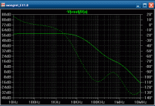
Second , I did an open loop gain test ... respectable 63db , pretty high gain.
I did notice this amp sucks for phase margin ( It is on the verge of being an oscillator - attachment 1).
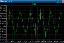
I also saw that the operating points of the amp were "off" (saturation glitches at the peaks - attachment 2). This would certainly give this amp a "tinny" 3rd/5th/7th harmonic signature.
BTW , I did all these assessments with 1 pair mjl4302/4281 BJT this amps Vbe is NOT designed for BJT's as is.
OS
First off , it simulated the first time and it uses garden variety parts.
Second , I did an open loop gain test ... respectable 63db , pretty high gain.
I did notice this amp sucks for phase margin ( It is on the verge of being an oscillator - attachment 1).
I also saw that the operating points of the amp were "off" (saturation glitches at the peaks - attachment 2). This would certainly give this amp a "tinny" 3rd/5th/7th harmonic signature.
BTW , I did all these assessments with 1 pair mjl4302/4281 BJT this amps Vbe is NOT designed for BJT's as is.
This cap (lead compensation) makes the loop response even worse , most likely it was added to make up for the lousy engineering.What about raising the 20pF C15 capacitor to a higher value
OS
Attachments
Last edited:
- Status
- This old topic is closed. If you want to reopen this topic, contact a moderator using the "Report Post" button.
- Home
- Amplifiers
- Solid State
- Noobie needs help on ebay amplifier

