Thanks for the tip. I want to build monos aren't these stereo with the PSU on the same board?
Hello
Yes, they are stereo with the PSU on the same board.
Why mono ?
Bye
Gaetan
Hello
Yes, they are stereo with the PSU on the same board.
Why mono ?
Bye
Gaetan
separate power supplies
Hello Rabbitz and cjcc67
You should try the Naksa, they are module with a unique topology and affordable price, it's even sound better than the Aksa with the warmth of tube.
Check at the Aspen forum.
Bye
Gaetan
Yeah, I spotted the NAKSA over there. I don't think I need another amp as had too many and gave most away or sold them for next to nothing. I'm not a fan of tube sound but do like the AKSA where I can dial in how much harmonics I like. The amount I use is much less than the genuine AKSA and heads towards the lower levels in the LF55. I'll be doing this with the B-AKSA as well.
I haven't spotted anything on the NAKSA driving low impedance loads due to the higher 42V rails which I imagine would reduce the low impedance capabilities which is important for me as I do have some speakers from hell that dip to around 3R. If I understand it correctly as you increase rail voltage you get more power at 8R but less ability at 3R-4R. Hugh might have more info on this. IIRC, the AKSA 55 was good down to 3R6 with 35V rails.
Last edited:
how many do you need to order?
Hi cjcc,
There is not s simple answer. Different PCB maker have different pricing structures. Some charge per panel, some by the square inch and others have a setup cost plus $x per PCB. Postage costs work out significant and can work out as much as the cost of the PCBs (if the batch is small).
regards
Last edited:
Yeah, I spotted the NAKSA over there. I don't think I need another amp as had too many and gave most away or sold them for next to nothing. I'm not a fan of tube sound but do like the AKSA where I can dial in how much harmonics I like. The amount I use is much less than the genuine AKSA and heads towards the lower levels in the LF55. I'll be doing this with the B-AKSA as well.
I haven't spotted anything on the NAKSA driving low impedance loads due to the higher 42V rails which I imagine would reduce the low impedance capabilities which is important for me as I do have some speakers from hell that dip to around 3R. If I understand it correctly as you increase rail voltage you get more power at 8R but less ability at 3R-4R. Hugh might have more info on this. IIRC, the AKSA 55 was good down to 3R6 with 35V rails.
Hello
A way to be able to drive lower Z load are to put two output transistors in parallel.
I don't remember the lowest Z that the Naksa could drive, but if it's not 3R, Hugh can say if he do mods on the Naksa for low Z speakers.
Btw, which louspeakers you have ?
Bye
Gaetan
Last edited:
I used the links on you web page (you have been busy) and tried some so i got an idea. i liked the look of custom PCB. A lot cheaper than i expected. 50 boards is quite reasonable. I'd use 4 myself.Hi cjcc,
There is not s simple answer. Different PCB maker have different pricing structures. Some charge per panel, some by the square inch and others have a setup cost plus $x per PCB. Postage costs work out significant and can work out as much as the cost of the PCBs (if the batch is small).
regards
NAKSAs will go down to 4R, not lower, but the rail voltage can be reduced for low Z loads.
Alternative is to beef up the amp for more power, something I'm doing right now.
Alternative is to beef up the amp for more power, something I'm doing right now.
Thanks for that information Hugh. Would the same apply with the B-AKSA using 42V rails?
I have a 30VAC transformer and get around 45VDC rails no load so I imagine too hot for this amp?
I have a 30VAC transformer and get around 45VDC rails no load so I imagine too hot for this amp?
Btw, which louspeakers you have ?
Bye
Gaetan
Gaetan
The main offending speaker that I use with the AKSA is one using 810921 + 18W8531G00 + M22WR-09-08.
Nah, Peter,
With 42V rails (used on the NAKSA) I would not go below 4R.
You could do it OK if the amp were only ever used at moderate levels, but one must design ultra-conservatively, since people find all sorts of ways to push the envelope, and if it blows, the designer is always at fault!
Hugh
With 42V rails (used on the NAKSA) I would not go below 4R.
You could do it OK if the amp were only ever used at moderate levels, but one must design ultra-conservatively, since people find all sorts of ways to push the envelope, and if it blows, the designer is always at fault!
Hugh
Member
Joined 2009
Paid Member
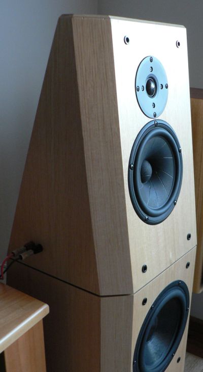
Rabbitz - nice looking speaker, is this something you have posted details about somewhere else on the forum ?
Thanks. No details on the forum, just a few pics. Design details were on my website but that's now closed.
Started as an OB for the 18W8531G00 (hence the odd shape) but now is a sealed enclosure. Had a Scan Speak tweeter originally but changed to the 810921. It's a 2.5 way electrically with an AR series crossover and the bottom woofer is vented.
Started as an OB for the 18W8531G00 (hence the odd shape) but now is a sealed enclosure. Had a Scan Speak tweeter originally but changed to the 810921. It's a 2.5 way electrically with an AR series crossover and the bottom woofer is vented.
Hi rabbitzI'm not a fan of tube sound but do like the AKSA where I can dial in how much harmonics I like.
How do you mean you can dial in the amount of harmonics??
.. you make modifications to the original boards?
Kind regards Baldin
I can recommend Olimex ... I have used them a number of times. It's cheap, high quality, and you can make them cut the boards, so you can fit as many PCBs (also different) on a given size board type (10x16 cm or 20x32 cm).how many do you need to order?
Minimum order is only one 10x16 cm board!!
Hi rabbitz
How do you mean you can dial in the amount of harmonics??
I'm sworn to secrecy. See post #49 & #61
http://www.diyaudio.com/forums/solid-state/168554-based-hugh-deans-aksa-55-a-4.html#post2220059
.... There is a hidden mechanism in the AKSA and I challenge anyone here to find it. Only two people in over ten years have twigged to it; it really is quite subtle. Rabbitz, nothing outta you, pal!!
......
Cheers,
Hugh
It seems there is a high frequency feedback from VAS to negative input og the LTP, formed by a resistor of approx 500k and a small cap, propably 10p - 100p, in series.
In LTSpice this does give some extra distortion, and by lowering the resistor you'll get mor distortion.
I think this is what you are refering to ... or?
But playing some with LTSpice with this, I find that the FFT does look a bit odd though.
You do get higher readings on the .four calculation, but the FFT window shows this as a kind of raised noise floor. 😕
The same effect, can be found to appear by incresing the input low pass cap (but somewhat depending of the design, but quite consistent).
So do you actually measure a higher distortion, or is some of this actually some artefacts from the FFT calculation.
I also find that playing more with the FFT parameters, points and window size, does affect the calculated distortion quite a bit ... which is maybe not so supprising 😉
Maybe someone with more insights to FFT algorithms can help here .... I might be wrong.
Best Regards Baldin 🙂
Last edited:
Edit: by using 1048576 points in the FFT and a Blackman window (options in the "Select what waverforms to include in FFT" window) you can get much clearer distortion readings ... it is clear that this trick works 😉 (and you do not get the same effect by changing the input LP filter cap) ...
I guess this trick can be tried/used on a lot of other amp designs ....
/Baldin 🙂
I guess this trick can be tried/used on a lot of other amp designs ....
/Baldin 🙂
It seems there is a high frequency feedback from VAS to negative input og the LTP, formed by a resistor of approx 500k and a small cap, propably 10p - 100p, in series.
In LTSpice this does give some extra distortion, and by lowering the resistor you'll get mor distortion.
I think this is what you are refering to ... or?
But playing some with LTSpice with this, I find that the FFT does look a bit odd though.
You do get higher readings on the .four calculation, but the FFT window shows this as a kind of raised noise floor. 😕
The same effect, can be found to appear by incresing the input low pass cap (but somewhat depending of the design, but quite consistent).
So do you actually measure a higher distortion, or is some of this actually some artefacts from the FFT calculation.
I also find that playing more with the FFT parameters, points and window size, does affect the calculated distortion quite a bit ... which is maybe not so supprising 😉
Maybe someone with more insights to FFT algorithms can help here .... I might be wrong.
Best Regards Baldin 🙂
I dont think this is it, what youre refering to is just plain feedforward compensation, I have used it for 25 years and still do, it was used by JLH on his more complicated designs and its something that he probably came up with as I havent been able to find anything predating him about this yet. This isnt anything new, Nelson Pass has also used it on Adcom amps and it works on all topologies.
- Home
- Amplifiers
- Solid State
- Based on Hugh Dean's AKSA 55