Ian,
Base stoppers slow the passage of charge into and from the base of the transistor, thus slowing it down a little and preventing HF oscillation. The base stoppers on the output stage devices, driver and main, do reduce transconductance a little, but this is absorbed by the negative feedback loop and it serves also to reduce OLG, reducing loop gain and further enhancing stability. A very useful tool; sonically base stoppers tend to 'soften' the sound a little, which in a SS amp is often necessary.
Stoppers are also used with tubes on their grids, so it's quite a widely used trick.
Hugh
I never thought to ask where those stoppers came from...sim? perhaps I shouldn't ask either...(secrets...voodoo etc.)
Folklore seems to be a reasonable guess. The rationale is to neutralize an occasional negative impedance that appears, looking into the base when the emitter is looking into a reactive (maybe capacitive) load. I've run other circuits through the sims, and many do require a 2.2 to 10 ohm base-stopper to stabilize them on transients. It has minimal impact on sonics, so you might as well have them by default on any Self EF.
Quote from Randy Slone: In some paralleled output OPS designs, base-stopper resistors are used in the base circuits of paralleled output transistors to improve stability and reduce the change of RF oscillation. Base-stopper resistors are typically about 1 to 100 ohms in value, with typical values in the 2.2 to 10 ohm range. Don't confuse base-stopper resistors with resistors placed in the base circuits of single-pair output transistors (i.e. non-paralleled output transistor pairs). In this latter case, the resistors are used to increase the input impedance of the output devices, thus reducing loading distortion imposed on the VA. In contrast, the function of the base-stopper resistors is to isolate the base capacitance of paralleled output BJTs. For the most part, base-stoppers resistors are not needed in BJT OPS. Many designers incorporate them as an added safeguard of OPS stability, but their effectiveness in most designs is questionable.
I don't know if we have determined the best place for the speed-up capacitor yet, but I am learning a bit more about base-stoppers.
 What do you think about Randy's view point?
BTW: Slone and Self refer to the suck-out capacitor as a speed-up capacitor. By sucking out the charge from the base of the OPS transistors, it is speeding-up their operation. Same thing.
regards
Last edited:
but their effectiveness in most designs is questionable.
B _S , they (basestoppers) increase the stability considerably. Not only on the OPS bases (2.2R to 4.7R) but the drivers as well (22 to 100R).
This was solved in this thread ... http://www.diyaudio.com/forums/solid-state/149324-self-type-3-ef-hybrid-triple-any-pointers-8.html for a triple ,which is much more "touchy".
Slone and Self refer to the suck-out capacitor as a speed-up capacitor. By sucking out the charge from the base of the OPS transistors, it is speeding-up their operation. Same thing.
"Suckout" caps work well. An active (CCS) based suckout works twice as well. Two interesting side-effects of this method is increased stability and no Xover distortion (no cutoff )up to medium power.
OS
Pete,
My experience matches yours here. I too tried CCS suckout schemas with Colin Brown in BC and we found they were most effective. And stoppers do considerably reduce transconductance of the output stage, leading to lower loop gain, quite apart from counterbalancing that critical area of negative base input impedance LG points out can really send an amp crazy.....
Hugh
Hmm, thanks for the last word on base resistors, guys. Perhaps I should have been clearer in my reference to the process of how those particular ones got onto the B schematic. That is a different question and it interests me. My reference to dark arts is a gentle nudge regarding the shrouded evolution of Gregs 'B'. It certainly drew the artillery though!
Readers of Randy Slone may have been confused about the seemingly common practice in the US of calling OP transistors drivers and drivers pre-drivers. A displaced ranking, if you like. What happens with triples requiring pre-pre-drivers becomes amusing.
Care needs to be taken with the text when he discusses these base resistors which are not to be confused...etc which should actually not now be doubly confused... Well, the ones to consider are in the VAS signal leads to the output stage, usually around 100 ohms. It is easier to define them that way, faced with this text quoted.
I will accept criticism for this. Show how his note re: confusion clarifies anything.
Last edited:
Hi All,
It is very clear in Randy's book that he is referring to EF II topology (i.e. the B-AKSA with a speed-up cap). The section the quote was taken from was "Paralleled Output Stages" and the referenced Figure 6.5a is a Paralleled version of the Improved EF output stage (Self calls it EF II). He also uses the standard terminology through-out his book.
regards
Thanks, Greg
Let me say that I have no argument with Randys informative works and style. His contribution to DIY speciifically is enormous and I remain his student.
The highlighted text I refer to, and it won't copy here, is:
"Don't confuse base-stopper resistors with resistors placed in the base circuits of single-pair output transistors. (ie non-paralleled output transistor pairs) In this latter case the resistors are used to increase the input impedance of the output devices.." etc.
I can only conclude here that these ~100 ohm resistors, as opposed to base stopper resistors, placed in the base circuits of single-pair output transistors are just that; in the bases of output transistors. They are not. I think he means the bases of the drivers to increase their input impedance, no?
Paralleled or single pair , OP or driver, a basestopper is a basestopper. an example is worth a 1K words (attachment 1) .
This OPS was brought to instability with reduced Cdom and excessive OLG , the 6 resistors either stopped the oscillation or reduced it to a damped state. Not recommended to do this with a real amp.
Bob cordell from my thread... http://www.diyaudio.com/forums/solid-state/149324-self-type-3-ef-hybrid-triple-any-pointers-4.html
OS
(attachment 1) .This OPS was brought to instability with reduced Cdom and excessive OLG , the 6 resistors either stopped the oscillation or reduced it to a damped state. Not recommended to do this with a real amp.
Bob cordell from my thread... http://www.diyaudio.com/forums/solid-state/149324-self-type-3-ef-hybrid-triple-any-pointers-4.html
a couple ohms base stopper in each output transistor isolates the driver from the load and base-collector capacitance of the output transistor. A few tens of ohms in the base of the driver isolates the pre-driver from the base-collector capacitance of the driver and any negative resistance at its base. Even 100 ohms is not bad to put in the base of the pre-driver to isolate it from the VAS. These low values of resistance will usually not seriously compromise the bandwidth of the stage (no shunt capacitors added).
OS
Attachments
Last edited:
Hi Os,
Things have been a little subdued here. I thought I might add that there is no real quarrel here with the role of these resistors - just the (un)clarity of the text.
I think whether to call the capacitor used here "speed-up" or "suck-out" is more down to social than technical reasons.
Things have been a little subdued here. I thought I might add that there is no real quarrel here with the role of these resistors - just the (un)clarity of the text.
I think whether to call the capacitor used here "speed-up" or "suck-out" is more down to social than technical reasons.
Hi Os,
Things have been a little subdued here. I thought I might add that there is no real quarrel here with the role of these resistors - just the (un)clarity of the text.
I think whether to call the capacitor used here "speed-up" or "suck-out" is more down to social than technical reasons.
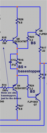
Yep, Ian, as you infer the base-stoppers are already there on the drivers (100 ohm) and the output transistors (10 ohm). I was hoping someone would clarify the ideal location of the speed-up capacitor but seeing that wasn't discussed too much I will make the decision to put it across the bases of the output transistors (like the "real" AKSA 55).
regards
Hi Greg, guys
I just looked back at the intro. to this thread and realized that yes, there was a point to these discussions. I believe it was to check the merits of compononent and circuit suggestions made in another thread. Some made here could be in the mix too.
Well, I would be surprised if the amps lined up on the heatsink back on page 1 had never been powered up and listened to. I guess there are plenty of other things that have to be done but this is the enjoyable part.
So, even if all the soundings are not done, nor the unobtanium caps and trannies arrived from outer Mongolia, I think a little report is in order. Of some interest might be:
1) The status of amps on test
2) Any basic (common) revisions you plan to
make to the schematic so far
3) Any different components already tested
4) Any findings that interest you subjectively or even (aarrggghhh)
measured results.
We'd love to know........
Hi Greg, guys
I just looked back at the intro. to this thread and realized that yes, there was a point to these discussions. I believe it was to check the merits of component and circuit suggestions made in another thread. Some made here could be in the mix too.
Well, I would be surprised if the amps lined up on the heatsink back on page 1 had never been powered up and listened to. I guess there are plenty of other things that have to be done but this is the enjoyable part.
So, even if all the soundings are not done, nor the unobtanium caps and trannies arrived from outer Mongolia, I think a little report is in order. Of some interest might be:
1) The status of amps on test
2) Any basic (common) revisions you plan to
make to the schematic so far
3) Any different components already tested
4) Any findings that interest you subjectively or even (aarrggghhh)
measured results.
We'd love to know........
Hi Ian,
Yes, the 3 amps on the heatsink have been fired up and listened to in the garage. The 2 identical amps using 2SC4793 and 2SA1837 drivers and KSA3505 VAS sound quite nice in the garage in mono on a test speaker. The third using BD139 and DB140 drivers and BD139 VAS doesn't sound as good. I have been alternating between the amps over the last 3 weeks and at least one of them has been running for a couple of hours each day. I have been monitoring the temperature of components and they appear to behaving themselves very well.
What I now realise is to do proper listening comparisons I really need to use my main system and in stereo. I have been designing a speaker protection board because I am a little afraid of blowing up my main speakers. During testing so far I have blown a few fuses by misconnecting or disconnecting the wrong wire at the wrong time. Luckily no damage to any of the amps or speakers.
I went to mount the heatsink in a case and found I had not tapped the holes that I had drilled in the heatsink. I bought a dozen of these heatsinks a few years ago and thought I have drilled and tapped all the holes, but I did break a tap so I must have stopped in disgust. Anyway I need to move these amps onto another heatsink that I have finished preparing today.
Alternative components? As you know I have been preparing list of alternative transistors, see VAS Transistors. This has side-tracked me a little, but I have been accumulating datasheets and lists of transistor data for years and I think it is worthwhile to formalise it a bit and get it more organised. It will help with this project and other future projects. I have already purchased various input, driver and output transistors to test. I am a bit undecided on alternative caps and resistors although I have been studying options on-line and in catalogues.
I have started the next 3 amps, 1 is almost complete and the other 2 are just a couple of plastic pages full of components. While I am building amp number 4, I am preparing the documentation, such as BOM, construction guide and setup instructions. A "draft" can be seen here B-AKSA 55. It will be a few more days or a week until it is in a usable form, but I have started and I have some more hand written notes that need to updated to my web site. A website is a good method of publishing filtered information. I hope it will be concise and properly structured. If people actually start building these amps I wanted to have this site available to answer the questions because I am bad at support via emails.
Another option. I have a JLH regulator, see JLH Add-on Shunt Regulator, that I am preparing for powering front end of these amps in the future. I do have a doubt about the operation of the bootstrap in this scenario, but I've find out one way or another.
I have an updated schematic but it is not available yet. It will have the revisions as discussed in this thread and I hope to include test voltages after the construction of amp #4.
I have my signal generator, dummy load and oscilloscope ready but I haven't tested any of these amps yet. Maybe amp #4.
regards
Well, I'll be....
Thanks Greg. I guessed you would be on the task this afternoon from your other thread. This is great. We get a free front row seat on the procedings as it were. It's interesting that you picked up a difference with the driver/Vas types.
I realise that the professor would require a rematch with BD types sequentially in each amp, double blinded and a squad of listeners but I'm quite happy with your summation.
Speaker Concerns:
You know, those crafty Canucks have some great full range speaker ideas that might make excellent low cost test drivers in basic, unfinished form for the garage. I'm not considering efficiency here, just simplicity and a quick driver phase solution. Maybe Bigun would like to comment.
Alternatively, I can vouch for the performance of SC's newest universal protector from Altronics as fitted to the class A amp. Spade terminals everywhere. 10 amp contacts, 24v coil and more - DIY delight. No, I'm not on the payroll with either business, unfortunately.
Thanks again for a comprehensive review. We are all interested to see how you go.
Ian
Well, I'll be....
Thanks Greg. I guessed you would be on the task this afternoon from your other thread. This is great. We get a free front row seat on the procedings as it were. It's interesting that you picked up a difference with the driver/Vas types.
I realise that the professor would require a rematch with BD types sequentially in each amp, double blinded and a squad of listeners but I'm quite happy with your summation.
Speaker Concerns:
You know, those crafty Canucks have some great full range speaker ideas that might make excellent low cost test drivers in basic, unfinished form for the garage. I'm not considering efficiency here, just simplicity and a quick driver phase solution. Maybe Bigun would like to comment.
Alternatively, I can vouch for the performance of SC's newest universal protector from Altronics as fitted to the class A amp. Spade terminals everywhere. 10 amp contacts, 24v coil and more - DIY delight. No, I'm not on the payroll with either business, unfortunately.
Thanks again for a comprehensive review. We are all interested to see how you go.
Ian
Hi Ian,
I have Bose 401's in the garage, not exactly hifi but you can get a rough idea, and because they are crap speakers it is impossible to blow them up. As the benchmark will be a real AKSA 55N+ I really need better speakers to hear the subtleties.
Thanks for the feedback on the SC universal protector. I have a folder with about 10 designs and that is one of them. I have pinched their choice of really plus I have many spades as well. Mine is based on the uPC1237 IC. It seems a little ridiculous spending so much time designing and building my own, seeing you can get the SC one for $20 or $30.
On the DB139/DB140 drivers issue, because I made the schematic with these and I wanted to see what happens if someone followed my original schematic. I must admit, I have a preconceived idea that they would be bad so that could be influencing my results. I have built a few amps with inferior drivers and VAS and they have always been a disappointment.
regards
Have you missed out taking your anti dyslexic pills lately ?
You keep posting DB139/DB140 instead of BD139/BD140 lately.
Oops. A friend just gave me this subtle reminder. Sorry for any confusion. I just worked out how to add these transistors to my spell checker so it will never happen again.
regards
Spice simulation
Have anyone actually tried to simulate this .... using differnet transistors, but otherwise same same ....
0.1% @ 20k .... not that empressive .....
One thing though that surprised me a bit, is that there actually seems to be more odd order distortion rather than even ..... for a "tube like sound" I would guess that you should have predominent even order ...
Have not done anything to try to tweak things ... bias current of course have a big influence on overall distortion ...
Try it out
Attachments
I am new to this simulation software, but there an error reported in the log file, how can I solve this:
regards
Code:
Error on line 219 : .model ksc3503 npn ( level=2  is =2.0893e-14  bf =101.5  nf =1.0  br =7.655  nr =1.007  ise =4.3652e-14  ne =1.5  isc =1.2598e-9  nc =2.0  vaf =717.25  var =13.16  ikf =0.2512  ikr =0.0832  rb =2.98  rbm =0.001  irb =0.001  re =0.5305  rc =0.9  qco =0.05  rco =50.1187  vo =2.476  gamma =1.8231e-7  cje =6.6039e-11  vje =0.7017  mje =0.3253  fc =0.5  cjc =6.6072e-12  vjc =0.5  mjc =0.2439  xcjc =0.6488  xtb =1.4089  eg =1.2129  xti =3.0 )
	* Unrecognized parameter "nf" -- ignored
	* Unrecognized parameter "br" -- ignored
	* Unrecognized parameter "nr" -- ignored
	* Unrecognized parameter "ise" -- ignored
	* Unrecognized parameter "ne" -- ignored
	* Unrecognized parameter "isc" -- ignored
	* Unrecognized parameter "nc" -- ignored
	* Unrecognized parameter "vaf" -- ignored
	* Unrecognized parameter "var" -- ignored
	* Unrecognized parameter "ikf" -- ignored
	* Unrecognized parameter "ikr" -- ignored
	* Unrecognized parameter "rb" -- ignored
	* Unrecognized parameter "rbm" -- ignored
	* Unrecognized parameter "irb" -- ignored
	* Unrecognized parameter "rc" -- ignored
	* Unrecognized parameter "qco" -- ignored
	* Unrecognized parameter "rco" -- ignored
	* Unrecognized parameter "vo" -- ignored
	* Unrecognized parameter "gamma" -- ignored
	* Unrecognized parameter "vje" -- ignored
	* Unrecognized parameter "mje" -- ignored
	* Unrecognized parameter "fc" -- ignored
	* Unrecognized parameter "vjc" -- ignored
	* Unrecognized parameter "mjc" -- ignored
	* Unrecognized parameter "xtb" -- ignored
	* Unrecognized parameter "eg" -- ignored
	* Unrecognized parameter "xti" -- ignored
regards
- Home
- Amplifiers
- Solid State
- Based on Hugh Dean's AKSA 55