approximately six years later than Pioneer's SX-1000TW first SS Receiver follows Sansui's first solid state model TR-707A with the output power devices 2SC2261 from Sanken and output/driver transformers.
Who can post the schematic?
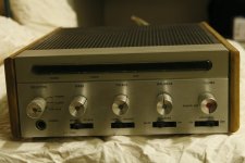
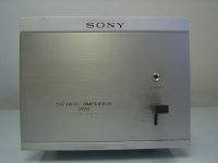
Looks like Sansui used the same case as the previous tube 220 and tube 250 amplifiers!
BTW - about
http://www.diyaudio.com/forums/swap-meet/165330-vintage-transistors.html
you will find pics of all transistors.
For the must types I don't find the asociated commercial vintage electronic devices like amps, TVs and SMPS models.
sorry that was the wrong URL - about the same name this topic exist at different files. here is the right URL (looks identical but it is an other URL):
http://www.diyaudio.com/forums/parts/167680-vintage-transistors.html#post2201610
I have found a test paper from the magazine to see by attachement, unfortunately with a lot of losses by read about "Finereader" (not through language translation!) A friend have send me this - unfortunately he has no longer the original paper -
also about this URL
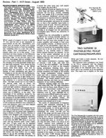
Article | Postscript on the Supreme 1 amplifier | Page125 - January1969 - Gramophone Archive
the losses are the same resp. even larger;
here the text:
====================================================
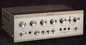
Trio Supreme 1 Stereo amplifier. Price: 298. Distributor: B. H. Morris & Co. (Radio) Ltd., 84-88 Nelson Street, London, El.
To the best of my knowledge the Trio Supreme 1 stereo amplifier is the only one on the British market which uses completely separate amplifiers for the bass, mid-range and high-frequencies although, whilst attending the recent Audio-Visual Equipment Exhibition in Paris, I heard Of other manufacturers who are proposing similar designs. Multi-channel amplifiers have been available previously and
I well remember the Sound Sales Tr-channel mono valve-operated system designed by the late Roy Wellington.
The Trio Supreme Is designed primarily for professional use for it requires modifications to the loudspeaker system in order to operate it correctly. Most loudspeakers consist of two or three drive units with built-in crossover filters. The filters in better equipment are complex and expensive ***, not only are they required to have a reasonably precise pass band, but they have to incorporate attenuators to match the acoustic outputs of the units.
The alternative approach as adopted by Trio is to use separate amplifiers to drive the bass, mid-range and tweeter speakers, six separate amplifiers for stereo. The following advantages accrue, It was each amplifier is directly connected to its own speaker unit, a high damping factor is maintained with a better transient response, (2) the amplifiers each cover a limited frequency range and this reduces intermodulation distortion. (3) it is difficult to design a cross-over filter using inductors and capacitors with a steep cut-off and (4) the individual volume controls for each channel enable one to balance the system for particular room acoustic conditions.
Thus, to use this amplifier correctly, one must either disconnect the built-in crossover networks on design an enclosure around three selected units. The amplifier is supplied with two colour coded. six-core cables terminated in wander plugs.
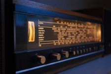
The Trio Supreme I amplifier is a most impressive design, beautifully engineered and finished in matt silver and brown, housed in a polished wood cabinet. The front panel carries the following controls: A row of six push-buttons selects the inputs, high and low level pickup, tape head, microphone tuner and auxiliary. Below is the mains on/off switch and tape monitor switch, to monitor a programme whilst recording. The mode rotary control has five positions: Mono, which parallels both channels, Reverse which switches, left enclosure to right and vice versa, Stereo. Left which provides mono reproduction only on the left loudspeaker, and Right which provides mono on the right speaker. The large volume control is mounted concentrically with the balance control. Four further rotary controls are for bass and treble of each channel and are calibrated in frequencies. Below these are four switches to control the fixed filters that operate at 40 and 80Hz, 2 and 5kHz, and 6 and 9 kHz, the central position in each case cancelling the effect of the variable controls.
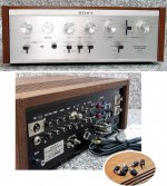
Beneath a hinged lower panel are a switch to select the appropriate sensitivity for the phono 2 input, left and right microphone jack sockets, tape play and record jack sockets, phase reversal switch for the loudspeakers. six volume controls for bass, middle and high speakers for each channel, calibrated in decibels.
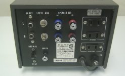
The back panel carries six pairs of terminals for the left and right loudspeakers. three 100W unswitched AC outlets, one 100W switched AC outlet. 2 Amp. fuse holder, fixed mains cable, separate earth terminal, DIN socket for tape play and record, six phono sockets for low level and six for high level inputs, two sockets for pie-amplifier output and two for recording output. Finally, two switches select bass cross-over at 400 or 800Hz and treble cross-over at 2,500 or 5,000 Hz.
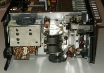
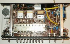
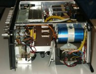
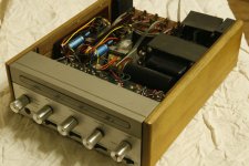
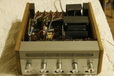
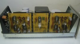
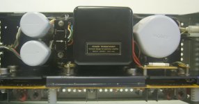
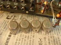
Removal of the Outer cover reveals a finds conceived and constructed chassis carrying a total of twelve separate amplifier printed circuit panels, two power rectifier panels and a highly stabilised regulator panel. The input circuits, tone control and filter stages are fully screened to keep spurious signals out of the highly sensitive amplifier. The pie-amplifier stages plug into each separate power amplifier. the mid-frequency and treble amplifiers being secured to the main chassis which assists as a heat sink. The bass amplifiers handle greater power and so considerably larger heat sinks arc' used. With a total of 53 silicon transistors one might expect that only a skilled engineer could find his way round the circuit yet the layout is so logical and clearly marked that one call follow it in a very short time.
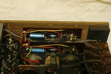
Every care has been taken to prevent earth loops and some quite massive earth conductors are used. The individual components are of very high quality and one would expect many years of trouble free operation. An interesting feature of each power amplifier is the automatic protection circuit which comes into operation immediately the circuit is overloaded. For example, if one applies a sine wave input to any circuit, observing the output across a dummy load with an oscilloscope, Specification and Test results: Trio Supreme I and gradually increases the input signal, the trace increases in amplitude then symmetrically starts clipping. Increasing the signal further suddenly causes the output to disappear and. after a few seconds, it re-appears. II the input signal is left at the overload level, the output switches on and off without causing any damage to the amplifier.
Performance tests
The accompanying graphs show: Fig. I the overall frequency ITSPOCISC and *** of the tone control circuits. Fig. 2 c-f-bet of the switched filters, and Fig. 3 the band pass characteristics of the individual amplifiers.
With such it complex amplifier. hearty hours were spent in measuring the various parameters and in general hey agreed wit Ii the maker .s specification. But it was not possible to agree with the power rating. The instruction manual suggesting that the total power available is 142 Watts RMS or *** Watts music power. Tests were made with dummy loads of * and 15 Ohms but. there don’t could reach the claimed power output by any amplifier. The signal clipped and the automatic overload circuit came into operation - IJstttg the Kelly
Tone-Burst generator. in which the input signal is switched oil iind cell at aiev require-ri time ratio, shigh tI higher posse outputs were' possible. Thus corder transient conditions one can approach I hr rat rn e'rl power but not lot long siesta i ne-rI Sigt cal
To its- the- ;eteplihe-r tcieder listening conditions. I usc-cl the bass radiator Irorn the- Bowers & \\ elicits l)M :3 r'e eclersure c:,osslng ovei at 400Hz tee it Greeeclnraees Axiette B ksr the reidfrequettci- iaugv and iii 5,000 Hz to it Kelly ribbon spea ke i. Spe-ake-c phasing might t be- it problem cc-line e- emits firint elilTcre'nt maimfactue ers crc- cacti. Frrtuuiatelv. the Northern polytechnic nceic t l cccl utre'cl a rema rkabltphase- teeeasureitccicc tenh made by EMT which enables estee- to please fee- various erciitr en it lnss secoetrls. Out eef phase enlils can cause distortion at I he- ereess-cever fre-q eee'nc\ and so. although theaigh the Tito a ntphiliet has it phase-- reversal switch. it is better to cnsulc the correct phasing a I thee etcelosstrc-.
I foecorl the e-Hsie'st ssay lee adjust the- aitiphcfiets 101 (iceestatit creatstir output level Was Lee use a gliding tom- re-cord ceitd, liv adjusting the individual vohtenee- eccictt ols for each band, one cotil ci e )btai ti it reason ably fiat Output, Ideally this should be rheetc ret ilic room destined for the le,udspeak e'rs. as room absorption clues Alert the- etppe-e tuenjeierecie's.
Fig. I Trio Supreme I frequency response and range of tone controls with treble filter at 2 and 5kHz (broken lines)
Fig. 2. Effect of boss and treble filters
Fig. 3. Band pass of individual amplifiers with crossovers switched as indicated
Having assembled the amplifier and loudspeaker system it was tried with various input signals. including the unique Trio supreme 20 photo-electric cartridge (reviewed in the lance-amy 1969 issue). The success of the system must depend oil the choice of' the separate I ciii dspea ke-r units and I found it difficult. riot impressible-. under dome-stir conditions tee hear any real advantage ni having two lots of three amplifiers and separate speakers. against two a mph tier channels and welldesigned enclosures with built-in crossovers. Admittedly the Trio hits one use speaker drive units of difl3-ring sensitivities, and gives a unique d egret- of individual control. But most integrated three-way speakers are probably best fell alone.
Thcrefoic it would appear to me that trier should marker it special enclosure housing three individual uitiis ne the same way that Sound Sale-s did sonic- IS years ago. Considering that oiiu is investing ne:-arl L300 in the amplifier. its main appeal will bv to the professional riser. for cvheni it has a considerably ss'icln'r range of facilities and control than any other amplificion the British market.
====================================================
Actually this amp devise is the predecessor of all later created Accuphase devices, as you can read here:
Accuphase: Facts, Discussion Forum, and Encyclopedia Article
more URLs
http://www.brunero.it/pdf/apparati_Kenwood.pdf
Kenwood Italy | Kenwood history > storia
Kenwood's größte Anlage Model 700 von 1975
Attachments

Last edited:
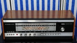
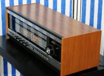
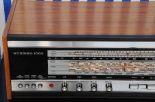
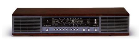
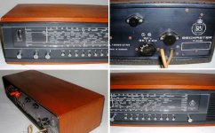
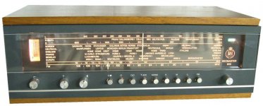
Körting Stereo 1000 equipped with 4x AD166
Not sure, whether it was the first Solit State receiver from Körting/Neckermann, but certainly one of the first. AD166 in the output stage, also in use in the "Metz 465" from post #41
Not sure, whether it was the first Solit State receiver from Körting/Neckermann, but certainly one of the first. AD166 in the output stage, also in use in the "Metz 465" from post #41
Attachments
-
 Körting Stereo 1000.jpg35.7 KB · Views: 495
 -
 Körting Stereo 1000 right.jpg37.5 KB · Views: 489
 -
 Körting Stereo 1000 front left.jpg42.1 KB · Views: 481
 -
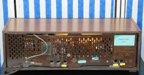 Körting Stereo 1000 rear.jpg38.3 KB · Views: 99
 -
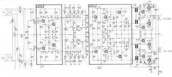 KORTING-STEREO-1000-SCHEM.jpg108.5 KB · Views: 219
 -
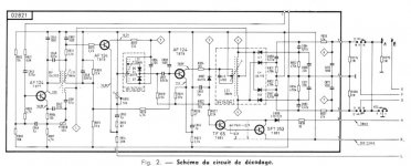 KORTING-STEREO-1000-DEC schem.jpg88.9 KB · Views: 189
 -
 Körting Stereo 1000 AD166.jpg4.8 KB · Views: 576
Last edited:
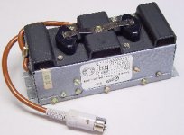
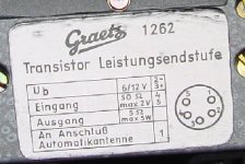
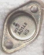
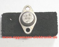
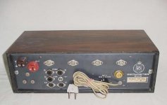
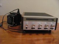
Graetz Monaural Power Amplifier from 1963 Model "1262" with AD139 or AD148
This power amp was a special offer for the universal car-audio/home audio/traveller mono reveiver "Super Page". Receiver and mono amplifier very hard to find.
From an other guy I have heard, that the sound was not loud, but very clear and tight both in the car and at home. Unfortunately he sell it for approximately 25 years
Graetz - Super Page
Transistorgeräte
Attachments
-
 Graetz_Power Amplifier_1262.jpg43.3 KB · Views: 159
 -
 Graetz_Power Amplifier_1262 rear.jpg41.4 KB · Views: 74
 -
 Graetz_Power Amplifier Package for 1262.jpg21.6 KB · Views: 55
 -
 Graetz AD148 Siemens.jpg5.6 KB · Views: 52
 -
 Graetz AD-148 Siemens.jpg120.2 KB · Views: 128
 -
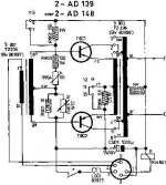 Graetz_Power Amplifier 1262 schema.jpg20.4 KB · Views: 122
 -
 Graetz AD139 Valvo.jpg6.7 KB · Views: 59
 -
 Graetz - Source for Power Amplifier_1262 .jpg18.9 KB · Views: 62
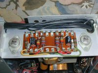
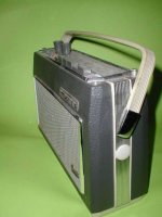
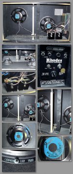
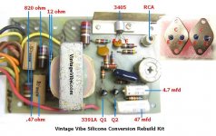
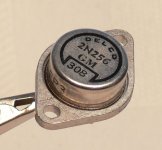
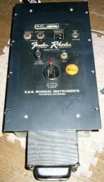
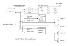
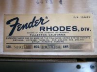
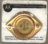
Fender Rhodes Mod 7054 Power output equipped with Delco DTG110
I have found this amp equipped with Delco DTG110 (also inside in Wurlitzer 140B)
Fender Rhodes¤Î¥ì¥¹¥È¥¢
Old Tech Vintage Synth Site - Fender Rhodes
http://www.vintagevibe.com/misc/rhodes pre amp board pic.jpg
I have found this amp equipped with Delco DTG110 (also inside in Wurlitzer 140B)
Fender Rhodes¤Î¥ì¥¹¥È¥¢
Old Tech Vintage Synth Site - Fender Rhodes
http://www.vintagevibe.com/misc/rhodes pre amp board pic.jpg
Attachments
-
 Fender Rhodos FR-7054 collection Delco TO-3 DTG110.jpg565.1 KB · Views: 94
 -
 Fender silicone conversion.JPG79.8 KB · Views: 80
 -
 Fender 2N256-Delco-3A.JPG93.2 KB · Views: 89
 -
 Fender Rhodes Power Amp connection face.jpg26.7 KB · Views: 70
 -
 Fender Rhodes Power Amp block diagram.jpg37.2 KB · Views: 69
 -
 Fender Rhodes logo external speaker cabinet.jpg27.3 KB · Views: 58
 -
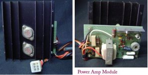 Fender Rhodes Power Amp Delco TO-3.jpg27.1 KB · Views: 61
 -
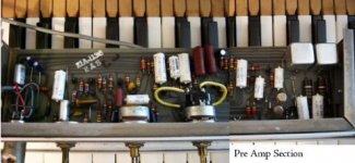 Fender Rhodes Pre Amp PCB.jpg23.7 KB · Views: 62
 -
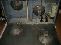 Fender Rhodes transducer cabinet.jpg24.1 KB · Views: 57
 -
 Fender Rhodes type aera Mod 7054.jpg15.8 KB · Views: 56
Last edited:
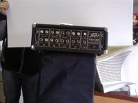
First Peavey's Solid State Amp: PA-120, Power BjT: 67292
Schematic about
http://www.peavey.com/media/pdf/manuals/pa120.pdf
More Infos:
http://www.diyaudio.com/forums/swap-meet/167439-vintage-peavey-pa-120-transistor-pa-amp.html
The Free Information Society - Peavey PA120 Preamp Electronic Circuit Schematic
Schematic about
http://www.peavey.com/media/pdf/manuals/pa120.pdf
More Infos:
http://www.diyaudio.com/forums/swap-meet/167439-vintage-peavey-pa-120-transistor-pa-amp.html
The Free Information Society - Peavey PA120 Preamp Electronic Circuit Schematic
Attachments
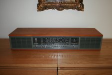
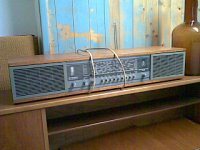
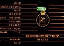
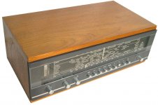
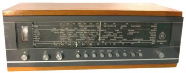
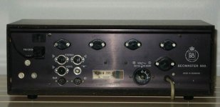
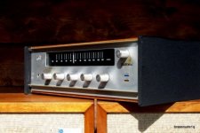
Beomaster 700, Beomaster 900 one of the first Solid State B & O Audio Components
Here some URLs and pics - no schematic to find.
It seems to be, that there are two different sizes of the Beomaster 900.
http://www.agsor.dk/hifi-1964.html
http://www.agsor.dk/hifi-1964.html
BANG OLUFSEN BEOLAB 1700 Service Manual free download, schematics, eeprom, repair info for electronics
Beomic : How Rare is It?
BeoMaster 900K, B&O, Expert, design, kvalitet
http://home.arcor.de/pfaue/klangkue/verstaerker/beo/beo900.htm
Minhembio.com - Hemma hos PeterForsell - Blandat!
Jrgen's Radio-Collection: Bang & Olufsen BeoMaster 900
AUDIO-C01
*** Beomaster 900 *** til salg på QXL.dk
Attachments
-
 Beomaster 900 front small-II.JPG74.5 KB · Views: 62
 -
 Beomaster 900 front small.JPG86.6 KB · Views: 62
 -
 Beomaster 900 front small version.jpg11.1 KB · Views: 63
 -
 beomaster700 coll.jpg75.7 KB · Views: 63
 -
 Beomaster 900 front operate.JPG64.5 KB · Views: 61
 -
 Beomaster 900 front advertisement.jpg121.1 KB · Views: 68
 -
Beomaster 900 data 4x AD139 1x 2N555 Mot.pdf116.5 KB · Views: 90
-
 Beomaster 900 front stereo Ind.JPG10.8 KB · Views: 62
 -
 Beomaster 900 front top view.jpg70.5 KB · Views: 46
 -
 Beomaster 900 front.JPG55.7 KB · Views: 52
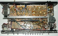
Beomaster 700, Beomaster 900 one of the first Solid State B & O Audio Components - II
Beomaster 700, Beomaster 900 one of the first Solid State B & O Audio Components - II
Beomaster 700, Beomaster 900 one of the first Solid State B & O Audio Components - II
Attachments
-
 Beomaster 900 open solder site.JPG81.1 KB · Views: 71
 -
 Beomaster 900 open FM front end.JPG56.9 KB · Views: 85
 -
 Beomaster 900 open comp site.JPG73.1 KB · Views: 78
 -
 Beomaster 900 operate.JPG93.6 KB · Views: 76
 -
 Beomaster 900 power supply.JPG62.6 KB · Views: 70
 -
 beomaster 900 rear 4x AD139 1x 2N555 Mot.jpg41.3 KB · Views: 69
 -
 beomaster 900 rear only 2N555 Mot.jpg6 KB · Views: 74
 -
 beomaster 900 rear only AD139 Valvo.jpg6.7 KB · Views: 68
 -
 Beomaster 900 rear TO-3 cover.JPG28.4 KB · Views: 56
 -
 Beomaster 900 speaker terminal.JPG115.2 KB · Views: 53
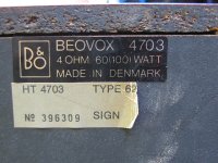
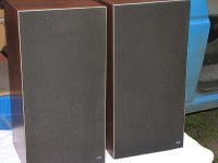
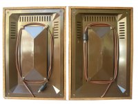
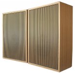
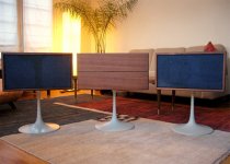
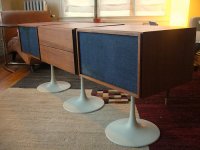
Loudspeakers for Beomaster 700 and Beomaster 900
Loudspeakers for Beomaster 700 and Beomaster 900
Loudspeakers for Beomaster 700 and Beomaster 900
Attachments
-
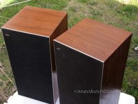 Beomaster 900 Speaker 2702 front top.jpg49.6 KB · Views: 654
 -
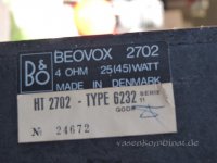 Beomaster 900 Speaker 2702 Typ aera.jpg47 KB · Views: 660
 -
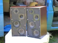 Beomaster 900 Speaker 2703 open.jpg44.3 KB · Views: 659
 -
 Beomaster 900 Speaker 2703 rear.jpg47.4 KB · Views: 652
 -
 Beomaster 900 Speaker 2703.jpg45.6 KB · Views: 632
 -
 Beomaster 900 speaker terminal.JPG115.2 KB · Views: 67
 -
 Beomaster 900 Speaker rear.JPG155.1 KB · Views: 68
 -
 Beomaster 900 Speaker front.JPG245 KB · Views: 54
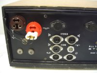
Electro Voice first Solid State Integrated Amp and Receiver - Bendix TO-3 "B10167"
The Electro Voice amplifiers 1144, 1179, 1244x and the receiver 1180 I discover by chance - I have never seen before. Looks very nice. Service manuals for two of this models you will find about
Service Manual free download,schematics,datasheets,eeprom bins,pcb,repair info for test equipment and electronics
No OTL topologies and germanium power devices in use.
About the 1144a you will find this one:
http://hifigoteborg.se/Electro-voice ev-1144a spec.htm
and here the 1144 pics:
Attachments
-
 E V - 1144 operation.jpg325 KB · Views: 91
 -
 E V - 1144-top view.jpg77.3 KB · Views: 96
 -
 E V - 1144 open buttom viev.jpg129.5 KB · Views: 102
 -
 E V - 1144 front right.jpg201.3 KB · Views: 106
 -
 E V - 1144 front IV.jpg89.4 KB · Views: 88
 -
 E V - 1144 front III.jpg343.3 KB · Views: 85
 -
 E V - 1144 Bendix 10167 open-I.jpg381.2 KB · Views: 117
 -
 E V - 1144 Bendix 10167 open-II.jpg350.7 KB · Views: 114
 -
 E V - 1144 Bendix 10167 open-III.jpg324 KB · Views: 112
 -
 E V - 1144 + Trafo.jpg85.3 KB · Views: 109
Last edited:
Electro Voice 1179, 1244x and the receiver 1180
Electro Voice 1179, 1244x and the receiver 1180
Electro Voice 1179, 1244x and the receiver 1180
Attachments
-
 E V - 1179 front Top.jpg91.9 KB · Views: 81
 -
 E V - 1179 on KLH27.jpg88.8 KB · Views: 83
 -
 E V - 1180 & Loudsp.jpg29.2 KB · Views: 86
 -
E V - 1180 front.pdf110.5 KB · Views: 121
-
 E V - 1180 front-II.jpg30.9 KB · Views: 62
 -
E V - 1244X Bendix 10167 front.pdf145.1 KB · Views: 117
-
E V - 1244X Bendix 10167 rear top.pdf182.1 KB · Views: 81
KLH twenty series - supplement to post #12 and #13
KLH twenty-seven, twenty-four and twenty-plus (twentyseven 27 twentyfour 24, and twenty+ 20+)
Schematics and service manuals so as inside photos wanted because not to find.
KLH twenty-seven, twenty-four and twenty-plus (twentyseven 27 twentyfour 24, and twenty+ 20+)
Schematics and service manuals so as inside photos wanted because not to find.
Attachments
-
 KLH 20+ incl speaker ii.jpg71.3 KB · Views: 83
 -
 KLH 20+ incl speaker.jpg124.6 KB · Views: 70
 -
 KLH 20+ top.jpg155.4 KB · Views: 71
 -
 KLH 24.jpg70.8 KB · Views: 79
 -
 KLH Thenty seven front.jpg36.7 KB · Views: 64
 -
 KLH Thenty seven front-II.jpg62.4 KB · Views: 74
 -
KLH twenty seven top bottom.pdf140.7 KB · Views: 94
-
KLH twenty seven rear front right.pdf98.2 KB · Views: 74
-
 KLH Thenty seven rear.jpg73.2 KB · Views: 66
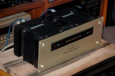
Model Fifteen 15 - first Solid State Power Amp from Marantz
Schematic wanted.
Schematic wanted.
Attachments
-
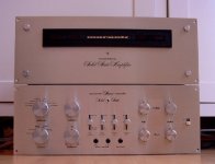 Marantz Model Fifteen front & Pre 7t.jpg297.8 KB · Views: 92
 -
 Marantz Model Fifteen fr left.jpg47.8 KB · Views: 92
 -
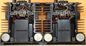 Marantz Model Fifteen bottom open.jpg105 KB · Views: 124
 -
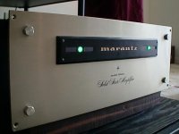 Marantz Model Fifteen front.jpg26.1 KB · Views: 121
 -
 Marantz Model Fifteen top open.jpg120.8 KB · Views: 127
 -
Marantz Model Fifteen top rear.pdf132.6 KB · Views: 96
-
 Marantz Model Fifteen.gif169.7 KB · Views: 123
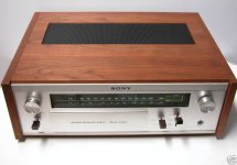
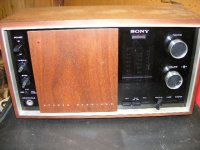
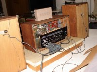
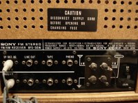
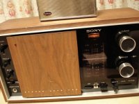
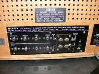
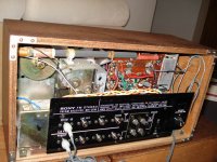
Sony's first Solid State Receiver: STR-6060F (FW), 8FS-40W and 8FS-50W
First the pics of STR6060F and STR-6060FW (STR6060FW)
First the pics of STR6060F and STR-6060FW (STR6060FW)
Attachments
-
 Sony STR-6060F front-II.jpg61 KB · Views: 75
 -
Sony STR-6060F open.pdf123.9 KB · Views: 143
-
Sony STR-6060F rear heatsink.pdf139.2 KB · Views: 107
-
 Sony STR-6060F top.jpg70.7 KB · Views: 78
 -
 Sony STR-6060FW front.jpg39.4 KB · Views: 104
 -
Sony STR-6060F type aera.pdf93.4 KB · Views: 116
-
Sony STR-6060FW open.pdf75.5 KB · Views: 112
-
Sony STR 6060F front open.pdf76.3 KB · Views: 97
-
Sony STR-6060FW rear top.pdf97.6 KB · Views: 94
-
 Sony STR-6060fw owners .gif35.1 KB · Views: 90
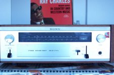
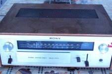
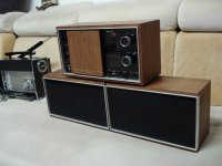
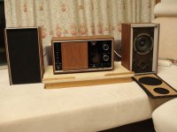
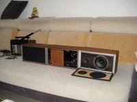
Sony's Stereo Receiver 8FS-40W and 8FS-50W
From the 8FS40W and 8FS50W I want schematics
From the 8FS40W and 8FS50W I want schematics
Attachments
-
Sony 8FS-40W.pdf112.6 KB · Views: 149
-
 Sony 8FS-50W + speaker.jpg60.7 KB · Views: 119
 -
 Sony 8FS-50W front & full range open.jpg65.2 KB · Views: 105
 -
 Sony 8FS-50W front.JPG115.5 KB · Views: 91
 -
 Sony 8FS-50W rear & speaker.jpg84.8 KB · Views: 101
 -
 Sony 8FS-50W rear chinch con.jpg108.8 KB · Views: 99
 -
 Sony 8FS-50W scale.jpg81.3 KB · Views: 96
 -
 Sony 8FS-50W rear.JPG108 KB · Views: 112
 -
 Sony 8FS-50W rear open.jpg114.3 KB · Views: 123
 -
 Sony 8FS-50W-I.JPG53.5 KB · Views: 119
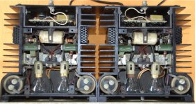
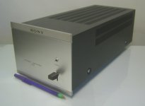
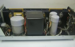
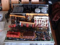
Sony's first Solid State Power Amplifier TA3120 and Integr. Vers. TA1080 with 2SD45
The reason for the later launched solid state versions than the US brands is the fact, that Sony don't like germanium power devices for the top quality audio components. Sony's 2SD45-2SD51 already silicon power devices. The TA-1080 and the TA-3120 launched 1965, while Sony's first solid state television about
Sony vintage transistor TV model 8-301-W and
http://www.tvhistory.tv/1961_Sony_8-301_AD.JPG
already introduced 1959
Attachments
-
 Sony TA-3120 1965 TO-3 2SD45 front.jpg71.4 KB · Views: 118
 -
 Sony TA-3120 front II 2SD45.jpg84.5 KB · Views: 86
 -
 Sony TA-3120 inside left 2SD45.jpg114.9 KB · Views: 123
 -
 Sony TA-3120 rear 2SD45.jpg105.1 KB · Views: 97
 -
 Sony TA-3120 open top 2SD45.jpg107.4 KB · Views: 97
 -
 Sony TA-3120 inside right 2SD45.jpg106.5 KB · Views: 105
 -
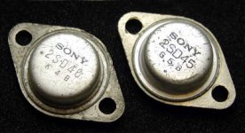 SONY_TR_2SD45.jpg22.8 KB · Views: 115
 -
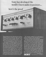
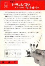 Sony Advertisement first Transistors.jpg43.5 KB · Views: 122
 -
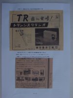 Sony Transistor Advertisementp119-a.jpg261.3 KB · Views: 89
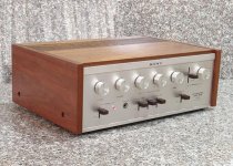
Sony's TA-1080 and TA-1120 from 1965
Sony's TA1080 and TA1120 TA1120F from 1965
SONY ƒXƒeƒŒƒIƒvƒŠƒ�ƒCƒ“ƒAƒ“ƒvTA-1080‚ÌŽd—l ƒ\ƒj�[
SONY ƒvƒŠƒ�ƒCƒ“ƒAƒ“ƒvTA-1120‚ÌŽd—l ƒ\ƒj�[
TA-1120 ??? - ??????????? - Yahoo!???
The TA-1080 uses the 2SD45 and the TA-1120/TA-1120F the 2SD45A in the output stage.
Sony's TA1080 and TA1120 TA1120F from 1965
SONY ƒXƒeƒŒƒIƒvƒŠƒ�ƒCƒ“ƒAƒ“ƒvTA-1080‚ÌŽd—l ƒ\ƒj�[
SONY ƒvƒŠƒ�ƒCƒ“ƒAƒ“ƒvTA-1120‚ÌŽd—l ƒ\ƒj�[
TA-1120 ??? - ??????????? - Yahoo!???
The TA-1080 uses the 2SD45 and the TA-1120/TA-1120F the 2SD45A in the output stage.
Attachments
-
Sony TA-1080 1965 advert 2SD45 TO-3.pdf67 KB · Views: 133
-
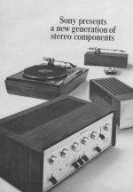 Sony TA-1080 first Solid State 1966 advert.jpg52.3 KB · Views: 117
 -
 Sony TA-1120-3120 1966 2SD45 advert.jpg79.6 KB · Views: 93
 -
 Sony TA-1120 inside.jpeg76.2 KB · Views: 133
 -
 Sony TA-1120 front-Ieft.jpg65.2 KB · Views: 109
 -
 Sony TA-1120 front.jpg64.6 KB · Views: 100
 -
 Sony TA-1120 front-II.jpg132.1 KB · Views: 125
 -
 Sony TA-1120 newer Silicon.jpeg77.5 KB · Views: 137
Last edited:
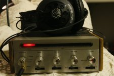
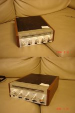
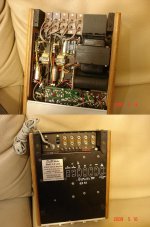
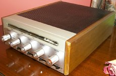
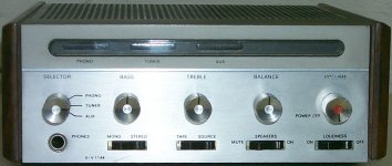
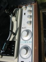
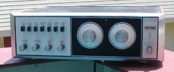
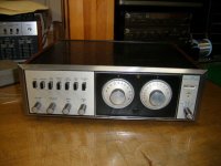
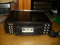
Very first HiFi Solid State? Transis-Tronics (Transistronics, TEC) FM-15/S-15, 1962
TEC (Transistronics, Transis-Tronics, a corporation of California)
TEC FM-15/S-15 (FM stereo tuner/integrated OTL amp)
some sources write, that this model was the very first solid state amplifier for home audio. Pics are very hard to find. After find out the right exactly company name, I have find nevertheless a lot of Informations:
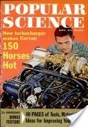
Popular Science - Google Bücher
URL from German "Google". If don't goes open, try this URL:
http://books.google.com/books?id=LC...onepage&q=Popular Science April. 1962&f=false
go to page 134 about previous URL
RARE TEC ALL TRANSISTOR FM TUNER MODEL FM-15 / S-15 (12/12/2007)...
Article | high fideli New York Hi-Fi Show, 1961 | Page120 - November1961 - Gramophone Archive
(TEC New York HiFi Show 1961)
Article | AUDIO NEWS PREPARED FOR THE GRAMOPHONE BY high fidelity | Page122 - November1960 - Gramophone Archive
audio-talk :: View topic - Transis-Tronics 'Clone'
- WTB: Schemos for Transis-tronics or Vico amps..
Biasing for transistorized (solid State") amplifiers with transformer for driving the output power devices (driver transformer) - patent No 3142807 (3,142,807) Transis-Tronics, a corporation of California, Filed June 4, 1962
Biasing means for transistorized amplifiers
Test in High Fidelity July 1961
High Fidelity Magazine Reviews Part 1
This TEC models mentioned also here:
DANIEL R.VON RECKLINGHAUSEN Quote AES Oct/Nov 1977 Vol 25 Number 10/11 pg 767
http://www.aes.org/aeshc/docs/vonreck_electronic-home-music.pdf
The first transistor high-fidelity amplifiers
were produced in 1961 by Transistronics [66], the model
TEC S15. A matching tuner, model TEC 15 MPx, was also
offered. In the following years a number of companies
offered transistorized music reproduction equipment.
[66] "Product Review Section, Amplifiers, Tuners,"
Audio, vol. 45, pP. 36-49 (Aug. 1961).
more TEC Types: Transistronics TEC-25 transistorized stereo amplifier
(also Widlar's 709 from Fairchild was mentioned,
OP-Amp first comercial use by Scott 1969)
About TEC's Solid State amp from 1961 model No "V-16" V16 no information to find (mentioned in an old german electronic magazine, perhaps thw wrong model No).
The same situation I note by the TEC "S-25" (S25)
TEC (Transistronics, Transis-Tronics, a corporation of California)
TEC FM-15/S-15 (FM stereo tuner/integrated OTL amp)
some sources write, that this model was the very first solid state amplifier for home audio. Pics are very hard to find. After find out the right exactly company name, I have find nevertheless a lot of Informations:
Popular Science - Google Bücher
URL from German "Google". If don't goes open, try this URL:
http://books.google.com/books?id=LC...onepage&q=Popular Science April. 1962&f=false
go to page 134 about previous URL
RARE TEC ALL TRANSISTOR FM TUNER MODEL FM-15 / S-15 (12/12/2007)...
Article | high fideli New York Hi-Fi Show, 1961 | Page120 - November1961 - Gramophone Archive
(TEC New York HiFi Show 1961)
Article | AUDIO NEWS PREPARED FOR THE GRAMOPHONE BY high fidelity | Page122 - November1960 - Gramophone Archive
audio-talk :: View topic - Transis-Tronics 'Clone'
- WTB: Schemos for Transis-tronics or Vico amps..
Biasing for transistorized (solid State") amplifiers with transformer for driving the output power devices (driver transformer) - patent No 3142807 (3,142,807) Transis-Tronics, a corporation of California, Filed June 4, 1962
Biasing means for transistorized amplifiers
Test in High Fidelity July 1961
High Fidelity Magazine Reviews Part 1
This TEC models mentioned also here:
DANIEL R.VON RECKLINGHAUSEN Quote AES Oct/Nov 1977 Vol 25 Number 10/11 pg 767
http://www.aes.org/aeshc/docs/vonreck_electronic-home-music.pdf
The first transistor high-fidelity amplifiers
were produced in 1961 by Transistronics [66], the model
TEC S15. A matching tuner, model TEC 15 MPx, was also
offered. In the following years a number of companies
offered transistorized music reproduction equipment.
[66] "Product Review Section, Amplifiers, Tuners,"
Audio, vol. 45, pP. 36-49 (Aug. 1961).
more TEC Types: Transistronics TEC-25 transistorized stereo amplifier
(also Widlar's 709 from Fairchild was mentioned,
OP-Amp first comercial use by Scott 1969)
About TEC's Solid State amp from 1961 model No "V-16" V16 no information to find (mentioned in an old german electronic magazine, perhaps thw wrong model No).
The same situation I note by the TEC "S-25" (S25)
Attachments
Last edited:
- Home
- Amplifiers
- Solid State
- Overview of Brands and Models from first Solid State Audio Amplifier Components want