In the real world, we have supplies having losses
The voltage will not be 100 volts anymore....and as a result, the power will also drop.
The ones feel the need to have more safety, or the ones will use rock stable power supplies or 2 ohms loads, these ones can increase the number of output pairs...distributing 60 watts maximum to each transistor, considering the consumption and not the output power....and this was written in this same thread.... my case was that voltage dropped and my power was reduced to 600 watts RMS.
To full power, using a powerfull SMPS supply, full power enter clipping.. no more than 15 pairs may be needed.. and this to continuous steady tone from generator.... when music is not that way....music is average.
I use to build and test.... this way i scape from the "I think so" reality to the "I know" reality...and everybody can do that, it is not my privilege...people must only to work hard, to hold soldering iron, using less speak and more action, working more than typping and talking.
This is the main difference we have folks...i am a buider...i use to check things in the real world...where i face real things... real supplies, real voltage drops.....i could not have a stable supply, as this is not easy in this range of power....so, only few pairs was used considering what gonna happens with almost everyone...exceptions will be considered separatelly, and some customized amplifier may be suggested,and directly, to the ones will use SMPS.
Will not be hard, nor clever customization, i will just ask the impedance the man will use and will increase the number of output pairs.
There's absolutelly no impeachment for you, while building, to use more power transistors and to apply the modifications you believe as good.
The schematic will remain the same...you do by yourselves your versions as you look very interested.... and enjoy a nice amplifier....not outsdanding! ... this one is only nice.
regards,
Carlos
Last edited:
1000W and 200Vdc
Hi all,
if these ill advised recommendations of Destroyer keep going, then someone is going to get hurt.
It must stop.
Destroyer is being irresponsible in promoting this schematic and this power by his methods.
If the only way to stop Destroyer is to close the thread, then I vote for closing the thread.
Carlos please read what is written several times: it is NOT the power dissipation. It is the combination of Ic and Vce that necessitates the paralleling. Please check out the SOA picture in the data sheet, that's the least you can do. Then calculate the Ic-Vce combinations that will occur in this amp driving a real world speaker with its phase shift. Please.
jd
jd
Wahab, SOA is not about power, it's the combination of Vce and Ic that is limited, even when it is a lot below the 'official' allowed power. The max dissipation is a DC spec. Check the SOA curve.
But hey, who am I to recite the data sheet. It is everybodies own choice what he wants to build, but if you lead people to a certain path, you also have a responsibility that goes further than trying to get the most followers.
jd
Agree , jan , but you should read that i m talking about
power dissipation of the devices.
I just wanted to point that it occur when the amp is
delivering half of its supply voltage and that this
value is the worst case in the dissipation curve , and
as, must be retained to determine the count of BJTS that
must be used to stay in SOA.
You will also noticed that i retained a value of 50W
for devices rated at 200W TDP ,since the datasheets
specify this very same SOA at 25° C, which is not
the case with an amp that see its OPS device gladly
reach 70/100C°.
That wasn t evident ?..i then must try to improve my
writing (lacks of?) skills...
Was tested real world Janneman...it is not a datasheet issue
Was tested, and i have used other transistors.... i suppose they are not that different, as they belong to the same family.
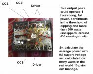
You see here the prototype, was tested...voltage has dropped, also power dropped naturally and was not the full power designed... you see that 5 output pairs (J4215 used, observe that some transistors are CCS and drivers) could manage to face 600 watts during one hour long (i used fan blower of course..the heatsink cannot face more than 250 watts of audio power...different than watts of heat).
If 5 pairs could manage 600 watts...then 10 pairs (suggested) will manage 1.2 Kilowatts...and the amplifier does not reach more than that unclipped...also supplies will have voltage drop... in real life this amplifier will not reach 900 watts RMS...so.... was tested folks!
And against real world there's no argument!
These transistors can manage to work with 180 volts peak to peak or i am wrong?
Maybe you are rigth if they cannot manage that...as this i could not test, my supply had voltage drops.
If then cannot, then i can replace them to MJL4281A..... them i will replace and will ask Alexmm to fix in the schematic and in the board layout.
Attached the MJL4281A and the working prototype.
regards,
Carlos
Was tested, and i have used other transistors.... i suppose they are not that different, as they belong to the same family.
You see here the prototype, was tested...voltage has dropped, also power dropped naturally and was not the full power designed... you see that 5 output pairs (J4215 used, observe that some transistors are CCS and drivers) could manage to face 600 watts during one hour long (i used fan blower of course..the heatsink cannot face more than 250 watts of audio power...different than watts of heat).
If 5 pairs could manage 600 watts...then 10 pairs (suggested) will manage 1.2 Kilowatts...and the amplifier does not reach more than that unclipped...also supplies will have voltage drop... in real life this amplifier will not reach 900 watts RMS...so.... was tested folks!
And against real world there's no argument!
These transistors can manage to work with 180 volts peak to peak or i am wrong?
Maybe you are rigth if they cannot manage that...as this i could not test, my supply had voltage drops.
If then cannot, then i can replace them to MJL4281A..... them i will replace and will ask Alexmm to fix in the schematic and in the board layout.
Attached the MJL4281A and the working prototype.
regards,
Carlos
Attachments
Last edited:
David Eather shows how to do this properly.Not all is true.
You forgot that the device only conduct 50% of the time,
Google and learn.
First post already shows the output pairs quantities
You should read a little in advance to post things.
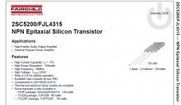
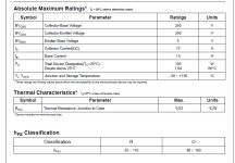
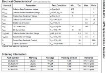
Here you have the J4215 and J4315 informations...datasheet is too much big to attach, but you can download it from the WEB.
regards,
Carlos
You should read a little in advance to post things.
Here you have the J4215 and J4315 informations...datasheet is too much big to attach, but you can download it from the WEB.
regards,
Carlos
Attachments
You should read a little in advance to post things.
Here you have the J4215 and J4315 informations...datasheet is too much big to attach, but you can download it from the WEB.
regards,
Carlos
Wrong Carlos, this does not show SOA. You DO understand SOA, don't you?
jd
It was built dear Janneman...do you think real world tests have no value?
Worked!...i cannot understand what you mean...sorry...maybe i am not skilled and i have to make it burn because theories.
You may be kidding...i will remember to laugh about latter.
regards,
Carlos
Worked!...i cannot understand what you mean...sorry...maybe i am not skilled and i have to make it burn because theories.
You may be kidding...i will remember to laugh about latter.
regards,
Carlos
Last edited:
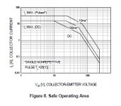
This is the Safe Operation Area curve. You can see that at the moment the Vce reaches 100V, the max allowed IC is about 500mA.
This needs to be coupled with the phase shift of a speaker load which will draw appreciable positive current even with Vout=0 or negative, so you can get the situation that Vce is larger than Vsupply and STILL the transistor has to deliver current.
It's hard to predict the max phase shift of a speaker; often designers use 45 or 60 degree as design worst-case value. It can all be calculated but it takes a bit more than this post. So, be conservative, and for 100V supply use LOTS of output devices in parallel. Or, maybe someone here can do the calculations.
jd
Attachments
I see....so, it is not safe...have worked with 98 volts positive and negative
over 8 ohms...when voltage drop is not that big.... had produced almost 500 watts, during one hour, with 5 output pairs..and it is not safe.
Not safe means that will burn?..... or means that will burn because the SOA wants to burn?
This is in the internet Janneman, now a days these informations are open to everyone to read.
Transistor Safe Operating Area
You are saying that is not good this way.... that is not safe..and i am saying real world have worked with many times more than 500 mA.... what is the meaning of this discussion?... want to prove my amplifier burned when it have not burned or the SOA was wrong to my samples (magic ones maybe).
Enjoy to predict things dear Janneman..i use to build, to test and to be sure.
regards,
Carlos
Last edited:
over 8 ohms...when voltage drop is not that big.... had produced almost 500 watts, during one hour, with 5 output pairs..and it is not safe.
Not safe means that will burn?..... or means that will burn because the SOA wants to burn?
This is in the internet Janneman, now a days these informations are open to everyone to read.
Transistor Safe Operating Area
You are saying that is not good this way.... that is not safe..and i am saying real world have worked with many times more than 500 mA.... what is the meaning of this discussion?... want to prove my amplifier burned when it have not burned or the SOA was wrong to my samples (magic ones maybe).
Enjoy to predict things dear Janneman..i use to build, to test and to be sure.
regards,
Carlos
Carlos I have no intention to continue this discussion. It's your responsibility, you do what you want.
jd
Thank you dear Janneman...i also do not like discussion
I want to be happy, to continue to enjoy life and to use the Safe Operational Area in this place you can see here....limiting space to dance, with this charming blonde.
Be happy, and welcome to my soa:
YouTube - Riu Palace Aruba Salsa Dancing
I am now busy, dreaming to dance with her.
Carlos
I want to be happy, to continue to enjoy life and to use the Safe Operational Area in this place you can see here....limiting space to dance, with this charming blonde.
Be happy, and welcome to my soa:
YouTube - Riu Palace Aruba Salsa Dancing
I am now busy, dreaming to dance with her.
Carlos
Last edited:
...parts replacements...
it's a hard discussion you got for a day...or was that arguement???...
with lots of engineers...
anyway, anyone would like to answer my question???...
carlos,
sir...
i believe some trannies are not locally available in our place or might just be very hard to find...
just in case what are the replacements for this trannies below???
BC 546 BP = ?
BC 818-40 = ?
MJE 15032 = ?
MJE 15033 = ?
can i use 2sc5200/2sa1943 instead of MJL 1302A/MJL 3281A???
salamat,
regards...
it's a hard discussion you got for a day...or was that arguement???...
with lots of engineers...
anyway, anyone would like to answer my question???...
Worked!...i cannot understand what you mean...sorry...maybe i am not skilled and i have to make it burn because theories.
You may be kidding...i will remember to laugh about latter.
regards,
Carlos
I do REAL WORLD tests everyday with my primary amp.
With only 4 output pairs and 2 pairs of speakers in parallel, my drivers (MJE15032/3) get HOT during parties and other occasions. I have used this amp for over 13 months , it does not lie IN THE REAL WORLD.My greatest concern is for safety , namely at 100V or even 70V with a 1KVA+ trafo. I send the kids outside and stand away from a power supply like this as through it was a BOMB.
My other concern is the drivers .... nowhere enough SOA to last 13 hours much less 13 months.Of course it may work for a hour. Even on that tiny junk heatsink. Physics must be different in S. america because even 250 watts makes for toasty warmth on my HUGE .05 C/w stealth heatsinks. NO ONE could never market or even call this thing a 1KW amplifier without using the Rob Elliot 117 method or one of the other ones I suggested.
At this deadly power level , to overdesign is more important than anything.
By janneman - Carlos I have no intention to continue this discussion. It's your responsibility, you do what you want.
It might be ours , too. I will say to everybody ,DO NOT BUILD THIS !!! IT IS JUNK and dangerous.
With just a few more transistors you could have a real safe amp that would last for years. The willingness of many other forum members to accept DX's misguided advice here and on his many other threads reflects the fact that there are MANY accidents in the waiting. My suggestion is for them to read Bob cordell's many interviews and other very valuable info available at DIYA.
I have just recently read all the DX threads and was aghast at the MAJOR quantities of outright dangerous misinformations contained within. I could start a whole new thread to discount these outright lies there are SO MANY.

This is not a personal attack , Carlos ..just a reality check for someone who has publicly accused me of stealing other forum members designs (DX original or symasym) , shown a unwillingness to discuss ANY changes or substitutes in your designs (all stolen) and publicly stated that I have no originality. Not all of us have access to BC-xxx transistors. I am very reasonable and will accept truths if they are explained in a civil manner and I WILL NOT HESITATE to point out something that is wrong.
OS
I am not an engineer dear Eesbiboi, and sometimes i feel glad i am not
Replacement suggestions.
This BC840 is the one reduces a lot distortion..but you can try a bigger one, alike MJE340/350.
To the drivers and CCS, you can use other transistors able to dissipate 10 watts and units that can face 200 volts or more from colector to emitter..there are millions of units you can use....current will not be the problem...and even the smaller one in To220 case will be able to face that current or more.
To the drivers you can even use the same transistors you use in the ouput..they can work fine there too, despite some small loss in gain...also i have used the power transistor as CCS to drivers.
BC546/556 can be substituted by 2N5401/5551 and other million of models, ancient and new models.
The output transistor may be units that can operate with more than 200 volts from colector to emitter, units able to face 5 amperes or more from colector to emitter, units to dissipate 100 watts or more.... so, these one you mentioned will fit...and other thousand transistors will fit too.
I am not the best one to suggest options of transistors, but at least i have tried to help...let's listen others....wait a little bit to see if other suggestions will be posted...as these guys are crazy to help..you see how they have jumped in the thread?... crazy to help maybe...we gonna see that soon.
Discussions man...people do not read the thread and come to discuss....i was already very damned with my amplifier and was screaming with the amplifier..saying why he have not burned when Mr. Soa arrived.
ahahahahahah!
Here we do not earn money..but at least we have lots of fun!
Dear Eesbiboi, i have a lot to do, and i cannot stay here for too long..will let you with these folks that for sure will work hard to help you.
Carlos
Attachments
Last edited:
it's a hard discussion you got for a day...or was that arguement???...
with lots of engineers...
anyway, anyone would like to answer my question???...
My point exactly , Carlos WILL NOT DISCUSS any part substitutions or changes to (HIS ??) designs . EESBIBOI ... don't build this one , google ESP AUDIO project 117 and build that.
As far as part substitution , one must always make other changes (emitter degeneration Resistors and other design considerations).I would suggest you proceed very carefully considering the fact that you even asked these questions concerning substitutions.
BC 546 BP = ? 2sa992/2sc1845 family
BC 818-40 = ? You really would not want to use this (VCeo of 40??
SMD??)MJE 15032 = ? 2sc4793
MJE 15033 = ? 2sa1837
Just get datasheets , compare Ic , Vceo , Hfe , take a peek at the evil SOA
 plot , aim for + 10-20%
As far as the outputs.. YES , don't waste your money , build ESP project 117 and be happy. happier , happy - est
OS
Replacement suggestions.
This BC840 is the one reduces a lot distortion..but you can try a bigger one, alike MJE340/350.
To the drivers and CCS, you can use other transistors able to dissipate 10 watts and units that can face 200 volts or more from colector to emitter..there are millions of units you can use....current will not be the problem...and even the smaller one in To220 case will be able to face that current or more.
To the drivers you can even use the same transistors you use in the ouput..they can work fine there too, despite some small loss in gain...also i have used the power transistor as CCS to drivers.
BC546/556 can be substituted by 2N5401/5551 and other million of models, ancient and new models.
The output transistor may be units that can operate with more than 200 volts from colector to emitter, units able to face 5 amperes or more from colector to emitter, units to dissipate 100 watts or more.... so, these one you mentioned will fit...and other millions of transistors will fit too.
I am not the best one to suggest options of transistors, but at least i have tried to help...let's listen others....wait a little bit to see if other suggestions will be posted...as these guys are crazy to help..you see how they have jumped in the thread?... crazy to help maybe...we gonna see that soon.
Discussions man...people do not read the thread and come to discuss....i was already very damned with my amplifier and was screaming with the amplifier..saying why he have not burned when Mr. Soa arrived.
ahahahahahah!
Here we do not earn money..but at least we have lots of fun!
Dear Eesbiboi, i have a lot to do, and i cannot stay here for too long..will let you with these folks that for sure will work hard to help you.
Carlos
BC840 / 2n5401 / Mje340-50 ... totally different devices to apply to this circuit. to use each in the current mirror will change the gain of the circuit which will have to be changed each time with the change in device. It would not be recommended to swap out devices in an unimformed way with a amplifier that is this deadly.
READ this .. Project 117
OS
- Status
- Not open for further replies.
- Home
- Amplifiers
- Solid State
- Dx Troyan, a 650 watts channel amplifier.