Made for my Greek friends..... dear Sakis and dear Fótios..... also to powerholic friends from our forum.
Was not assembled and tested....but, as supply voltage is the one i am using in the Fokker, also the circuit (exception is the V/I limiters)...and Fokker is playing here, at my home, all day long...i do not imagine a problem this one can produce....Fokker is dead stable at my home.
This VAS circuit gonna be tested with 100 volts soon...this is the circuit we have to be very carefull.
Supply power needed will be twice the output power..do not forget fuses in series with the output line..to speaker protection...also a protector will be a good idea to be used.
Output transistors..use the more modern ones....MJL21193 and others
Minimum of 6 pairs when using 8 ohms...better to use 10 pairs
Minimum of 8 pairs when using 4 ohms...better to use 12 pairs
Minimum of 10 pairs when using 4 ohms and entering distortion, 12 pairs
Minimum of 12 pairs when using 2 ohms and entering distortion, 14 pairs
Supply condensers..to 8 and 4 ohms, use 40 thousand plus 40 thousand microfarads.
I suggest you to use rail fuses..half the value used in the output line.
Use short cables, and thick cables from supply to the amplifier..if longer than 40 centimeters, then install, at least, 470uf each rail, near the power transistors colectors.
Heatsink, minimum size is 24 by 30 centimeters...having 24 fins, each one of them measuring 30 by 10 centimeters (high)... use fan blower to help to cool the monster down.
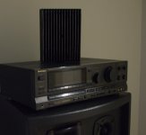
Picture shows Fokker amplifier... the technics is only a case to power supply..the heatsink is good for continuous full power over 8 ohms..not good for continuous in 4 ohms (but can hold music, can hold average power)...very small for 2 ohms operation.
Fokker is the same amplifier without the V/I limiter...and using 90 volts instead of 100 volts... Fokker sound is very good..the second best sound i have...first is the Dx Blame ST....this one was not assembled..but as Fokker is the same...we can understand that this one was assembled too.
regards,
Carlos
Was not assembled and tested....but, as supply voltage is the one i am using in the Fokker, also the circuit (exception is the V/I limiters)...and Fokker is playing here, at my home, all day long...i do not imagine a problem this one can produce....Fokker is dead stable at my home.
This VAS circuit gonna be tested with 100 volts soon...this is the circuit we have to be very carefull.
Supply power needed will be twice the output power..do not forget fuses in series with the output line..to speaker protection...also a protector will be a good idea to be used.
Output transistors..use the more modern ones....MJL21193 and others
Minimum of 6 pairs when using 8 ohms...better to use 10 pairs
Minimum of 8 pairs when using 4 ohms...better to use 12 pairs
Minimum of 10 pairs when using 4 ohms and entering distortion, 12 pairs
Minimum of 12 pairs when using 2 ohms and entering distortion, 14 pairs
Supply condensers..to 8 and 4 ohms, use 40 thousand plus 40 thousand microfarads.
I suggest you to use rail fuses..half the value used in the output line.
Use short cables, and thick cables from supply to the amplifier..if longer than 40 centimeters, then install, at least, 470uf each rail, near the power transistors colectors.
Heatsink, minimum size is 24 by 30 centimeters...having 24 fins, each one of them measuring 30 by 10 centimeters (high)... use fan blower to help to cool the monster down.
Picture shows Fokker amplifier... the technics is only a case to power supply..the heatsink is good for continuous full power over 8 ohms..not good for continuous in 4 ohms (but can hold music, can hold average power)...very small for 2 ohms operation.
Fokker is the same amplifier without the V/I limiter...and using 90 volts instead of 100 volts... Fokker sound is very good..the second best sound i have...first is the Dx Blame ST....this one was not assembled..but as Fokker is the same...we can understand that this one was assembled too.
regards,
Carlos
An externally hosted image should be here but it was not working when we last tested it.
Attachments
Last edited:
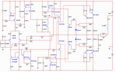
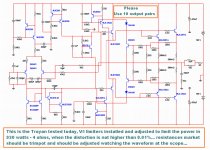
Schematic is showing only two output pairs, to show you
that each emitter resistance must have 220 ohms to the V/I limiter transistor base.
This V/I limiter is simple..you can make it better if you want...it is up to you.
I do not like, and i do not use..but there are controversies, so..here you have one using V/I limiter..be happy!
The real quantity of output pairs will depend you supply under load..your heatsink size, your impedance and the way you gonna use the amplifier..if to parties..full distortion..them we have to think about with some care.
Last post..you can see output transistor suggested quantities.
THIS AMPLIFIER IS NOT TO BE USED WITH 2 OUTPUT PAIRS.
regards,
Carlos
Attachments
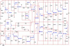
You can try better limiters...here you have one a little bit better
But there are others that interacts the positive with the negative... even better...this one will be tried in one of my amplifiers...just to check how better it is.
The values you see are not to Troyan.... this one is for 8 ohms, to a 70 volts supply amplifier, and the threshold when the limiter starts to work (sadly) is when the amplifier is having more than 42 volts rms over the speaker....in other works....more than 220 watts.
Then we can reduce the number of output transistors..as power will be limited..
Man!... you can used it...enjoy..... i will never use the stuff in my home amplifiers.... good to save money, to reduce power output, to reduce costs..and to reduce audio quality too.
regards,
Carlos
My comments without any attack:
1., Would you explain me how does the output protection works, and why it is better or more effective than a conventional circuit? What is the purpouse of the diodes there, and of the 220r resistors in the transistor's collectors?
2., Why are CCS-transistors's reference transistors are medium power MJE devices?
3., Why are the CCS-transistors of the drivers are power output devices?
4., What is the benefit of using 100n capacitors instead of ~100uF as filters in the CCS's reference circuit? 100nF does nothing with PSRR in these subcircuits.
5., What about the phenomenon called beta drop? Is a simple EF OP stage enough here?
6., Are you sure MJE15033/34 is an optimal driver pair here, to drive up to 12 pairs of OP devices?
7., Is really 15...18mA current needed for the CCS's references (2×5,6k, 2×6.8k)?
8., 750Wrms on a 4r speaker load produces 30A peaks. Think about it.
Anyway it looks OK, and should work, but probably it will sound muddy when pushed hard - if it not blowed yet.
I would never build it without modifications.
Don't forget, designing a such high power rated amplifier requires different type of knowledge and experiences then designing a small or medium audiophile amplifier.
If you don't like my comment, feel free to add me to your ignore list!
Ladies have not arrived yet.
A fast reading, seems to me you ask theories...i know nothing about that..and when i know i do not answer, or i use to say i do not know..because i do not like, and do not want to atract people that loves theories to transform the thread in a box ring.
I see you are new..registration from 2008 or 2009...do not know me..i am a long time here..have learned something..from here..also about people behavior too.
I have build some amplifiers..i am 59 years old..have studied something about electronics..but i am addicted to practice, to build and to listen...theories sometimes helps.... i use my skills, basic things learned..the amplifier is playing here with 90 volts..without E/I limiter...so..it works..this interests me more..the rest.
I do not know.
regards,
Carlos
Made for my Greek friends..... dear Sakis and dear Fótios..... also to powerholic friends from our forum.
Was not assembled and tested....but, as supply voltage is the one i am using in the Fokker, also the circuit (exception is the V/I limiters)...and Fokker is playing here, at my home, all day long...i do not imagine a problem this one can produce....Fokker is dead stable at my home.
This VAS circuit gonna be tested with 100 volts soon...this is the circuit we have to be very carefull.
Supply power needed will be twice the output power..do not forget fuses in series with the output line..to speaker protection...also a protector will be a good idea to be used.
Output transistors..use the more modern ones....MJL21193 and others
Minimum of 6 pairs when using 8 ohms...better to use 10 pairs
Minimum of 8 pairs when using 4 ohms...better to use 12 pairs
Minimum of 10 pairs when using 4 ohms and entering distortion, 12 pairs
Minimum of 12 pairs when using 2 ohms and entering distortion, 14 pairs
Supply condensers..to 8 and 4 ohms, use 40 thousand plus 40 thousand microfarads.
I suggest you to use rail fuses..half the value used in the output line.
Use short cables, and thick cables from supply to the amplifier..if longer than 40 centimeters, then install, at least, 470uf each rail, near the power transistors colectors.
Heatsink, minimum size is 24 by 30 centimeters...having 24 fins, each one of them measuring 30 by 10 centimeters (high)... use fan blower to help to cool the monster down.
Picture shows Fokker amplifier... the technics is only a case to power supply..the heatsink is good for continuous full power over 8 ohms..not good for continuous in 4 ohms (but can hold music, can hold average power)...very small for 2 ohms operation.
Fokker is the same amplifier without the V/I limiter...and using 90 volts instead of 100 volts... Fokker sound is very good..the second best sound i have...first is the Dx Blame ST....this one was not assembled..but as Fokker is the same...we can understand that this one was assembled too.
regards,
Carlos
An externally hosted image should be here but it was not working when we last tested it.
Carlos ! ............. Lower
 what about using 70V supply ? Is this PA amp or hi-fi amp ?
Reasons why i have made this amplifier
Aims to publish this amp.
Meet my friend Sakis desires, to verify the benefits of V/I limiter versus some losses of sonic quality... ... to produce a power amplifier for powerholics, fanatics by power .... show to a few rare and arrogant engineers, that anyone, armed with a calculator and basic knowledge of electronics can design amplifiers so dense and crowdy as they produce to show themselves off, ... and that these amplifiers almost always does not offer much advantage in the same ratio the multitude of sub circuits can induce us to think..
Tp demonstrate and prove that complexity and
multiplicity of circuits does not bring to you,
necessarily, superior sound quality .. demystify
and demystify (mystification and myth) that CCS
current mirror, sink current and voltage regulators
bring benefits.
Alert, underline and highlight, for starters, that
what provides energy to a power amplifier is the power supply, and from the power supply you will produce your output power, and the ratio of audio power produces and heat generated is dependend from the amplifier class only... the complexity and multiplicity of circuits does not generate more power, as audio power is a direct consequence of your power supply energy.
to be continued......
Last edited:
Why i have made these amplifier, Fokker and Troyan..almost the same, small variations
....... To show that a bad designer, beginner or inexperienced, always tend to refine the draft.. dense and crowdy circuits are signs or lack of
competence... as this increases production costs . having benefits that are
uncertainty, feeling unsafe, and having the desire to show to their communitty they know a lot, then some of them will create nainly visual complexity and multiplicity of circuits, there will be using all sorts of existing sub circuit, CCS, voltage regulator, current
sink, current mirror, V / I limiter ... and this ends up being one type of fee that is paid for the vanity of the designer and by their need to self promote, appear to be known to be famous... some of them, deepply unshamed, use tenths of resistances in parallel that can be substituted by few ones as a power transistor emitter resistances..just to increase the complexity to the fast eye inspection.
This amplifier, not only the Fokker, but also the Troyan, offers mainly power, and because it’s
supply voltage, not because of crowdy circuitry as you may know, the sound quality is very good, as any amplifier where the signal levels and polarization of the transistors is correct, or at least, not much wrong, but nothing extraordinary ... not nearly offers the sound of Dx Blame ST,
Prove that most people do not read the whole thread, which only make speed reading, a kind of dinamic reading was famous during the sixties, and will soon give their opinion, a criticism often moved by intimate, internal own needs, ironic post questions, use of sarcasm and doubts about the designer technical decisions token the same way they doubt about themselves, they post a reflection of their disturbed souls.. .. opine that the amplifier will not work when it is already working and playing good music... that opine that will burn, or explode, ... as they are burning inside because of envy, and exploding of angry because they could not do the same... when the amplifiert was tested full power and proved stable .... show that we have 220 thousand noble companions and some human waste too... thanks God, a minority... some poor souls lost in this world, by and accident of our destiny, landed in our wonderful forum bringing negativity and the worst human defects... third-class people, in what concerns the human qualities.... my amplifier is an alert..they will, probably, with enormous chances, produce an amplifier alike these crowdy ones i am showing you.
Regards,
Carlos
Last edited:
Schematic does not show you the correct quantity or output pairs
Each case may need your own study about how many pairs you gonna use..this depends your power supply performance (to me measured real life)...your heatsink used, the type of use you gonna give to it.
I can help if you need, to choice the number or output pairs.... the schematic diagram was simplified, showing few pairs only...more pairs will be needed.
regards,
Carlos
BC818-40 (Vce =25V) exposed to 200V !!! voltage swing in very strange conected VAS, no current limit in VAS ,what will happen, if V/A limiter is active (but it is with attached schematic with diodes 1N4148 impossible) ???.. Drivers loaded with CCS ,attempt to make class A drivers") , no real advantage with class B (AB) outpout..
, no real advantage with class B (AB) outpout..
Yes, it is really Troyan horse, potentialy very dangerous..It is only drawing, not real, working amplifier.
Carlos, be so kind and post e.g. snapshot from osciloscope screen showing limitation Have you any working prototype with posted schematic and components?.
Theories are here needed to transform ideas to working circuit.
, no real advantage with class B (AB) outpout..Yes, it is really Troyan horse, potentialy very dangerous..It is only drawing, not real, working amplifier.
Carlos, be so kind and post e.g. snapshot from osciloscope screen showing limitation Have you any working prototype with posted schematic and components?.
Theories are here needed to transform ideas to working circuit.
Last edited:
To my dear DIY friends..here you have some V/I limiters
All them from Electronic books we can have and read... Slone, Self, Ian R. Sinclair, Hood, Duncan, Brice, Singmin Davis,Patronis, Watkinson, Steven T. Karris editions,... and some other valuable help we can have..also in our forum we have special designers to help us to learn more.
Here you will see, something very important, the Waveform Pathology..the Fokker, the Troyan, shows the waveform number 9... despite of they have pointed that this means a very good performance..or indicates that..the Dx Blame ST, the best one in my point of view (the best i could even listen to) have perfect square waves, almost the same comes out from the generator.... the one sounds better... the first one, in my whole life, that measured very well and sounded very well too...thanks to Doctor Douglas Self....my hard work has helped a little too..as the CCS used in the Blameless was more a problem than a solution.
You will see several diagrams, from books, showing V/I limiters variations...several options you can use, have just to adjust resistances..anything more than that...of course i can help.
Non theoricall folks, builders, people that want to learn, people that want to help are welcome..if really want to help instead to shown themselves, and these ones, usually goes direct to my mail, as they want to help me..not needing to show themselves.
carlos.eugenio1951@yahoo.com
Wanna know why i did that or did those...ask me without show me the way you would do... because this is not a question, this is an answer.... and i have not asked.
regards,
Carlos
An externally hosted image should be here but it was not working when we last tested it.
Attachments

Thank you dear Wahab
I have just assembled the V/I limiters.... sadly i could not test using 100 volts..all i have is 90 volts....but i have used two supplies in paralell.... DC output in parallel..... now voltage is not dropping more than 12 percent..this is fine.
I have tried the limiters and adjusted them because of Sakis and some folks that may want to give a try.
I am using 10 output pairs..drivers and almost all CCS circuits are in the main heatsink... the CCS to the differential is not in the heatsink, this one does not overheat...transistor are the ones i have..of course then can be replaced by others, smaller ones, respecting current and voltage naturally.s
Power was limited in 930 watts at 4 ohms, and this i did at the simulator, i have not courage to do that using my speakers, also my dummy load cannot hold that power....i have tried and limited, to see the limiting action to 400 watts at 8 ohms to observe the V/I limiter performance...it really do the job but compresses the dinamics..limit the peak and this i really do not appreciated..so...was tested because of Sakis and some good friends we have in this forum, but disconnected in my own home amplifier.
Was tested, sounding very good..waveforms are fine... distortion is small while using 8 ohms (0.008%) and dinamics are great (off course, with all this huge power we feel deeply impressed).
From now on..only small modifications and capacitor tuning for sonics... small modification in the drivers current may be needed..to be around 23 miliamperes... we do that listening and also inspecting waveforms... and all that checked in the simulator (Multisim 10)
Temperature compensation is working fine.... it is working war during stand by.... around 8 degrees celsius above my home temperature (29)... pushing hard the temperature goes to almost 50 degrees..means my heatsing, the big black one is not doing the job..it is a 500 watts heatsink used to a Radio Frequency transmitter that dissipates continuous 500 watts without fan blower.
I forgot to mark the resistances that must be trimpot...the ones you see in the limiters, from the limiter transistor bases to the output line... 200 ohms... they should be 500 ohms trimpot.... adjustment of limiting power output must be done using a Osciloscope and watching the limiter operation to have a symetrical operation.
regards,
Carlos
Attachments
Acording schematics, simple I limiter is used, not V/I, here is no sensing of voltage acros output devices, e.g like here,
http://www.diyaudio.com/forums/atta...hannel-v-i-limiter-supply-rail-referenced.gif.
Output current limit is about 30A with 10 output pairs and showed componet values, also with accidently shorted output.So 3 A per device and 100V acros device at the same time. It is about 3 times more, than allowed by SOAR for used devices...It will be very expensive experience.
With this (unsuitable..) I limiter it is simply impossible get full power and at the same time ensure safety with shorted output. It must be clear visible in simulation.
And what about real, complex load , when current demands (and momentary power dissipation in output devices) can be much higher?
Last edited:
Here you have... any help will be welcome...as i am already creating the amplifier
The Fokker and Troyan (Fokker plus V/I limiter.. and more volts in the supply), will be delivered in July , 17th.
For a while i am listening (already built..ugly but working) and trying some minor modifications... trying different VAS and currents, tweaking some values..only small things...keeping CCS because this has a nice "appeal" to builders..they think this makes the amplifier sound good....so...let's give them what they want.
This is time to suggest things, beeing friendly, without criticise or trying to show yourselves will be welcome here if the idea is to help forum, and to help me to help forum first...to exercise the passion by second, and to serve our own pride by third.
I cannot guarantee i will do whatever you suggest, as this may be a remote control system...people push the button and uncle Charlie move.... but some ideas i may feel interesting i may try..but this is not a promess... as alike everybody i am stubborn and biased.
Part number attached...if not trying to give one on me..then i will be full kindness and attention with all of us.
Remember..alike you i am still learning... we are always learning some.
regards,
Carlos
Attachments
- Status
- Not open for further replies.
- Home
- Amplifiers
- Solid State
- Dx Troyan, a 650 watts channel amplifier.