Stupid question maybe...
is it possible to make a darlington or a sziklai pair with
the silicium transistor as driver and the germanium transistor as power device.
and vice versa.
and is the base-emitter voltage then 0.65+0.25=0.90 or 0.25+0.65=0.90 in a darlington configuration.
and in the sziklai configuration does is remain that of the driver transistor
so 0.25 for germanium or 0.65 for silicium.
weird question i know, not the daily stuff but if someone knows the answer
it would help me alot
Thanks
I did it long time ago, using germanium power (ASZ family) in a asymetric configuration (I had only "pnp" type). The bad part was the thermal stability - it was hard to compensate and the germanium power trz where very sensitive to overheating. I burned up a lot of them due to thermal run-up.
Eventually I switched to Si and never looked back.
Eventually I switched to Si and never looked back.
Can't say i have ever even thought about it until you brought up the subject
I don't see why it can't be done, though i'll happily stand corrected.
I feel sure it'd work both ways to, with either the germanium device as either the driver or output. The only thing i can think of is the different saturation voltages (collector to base) of the different devices. By the way, i have never worked with Germanium so i might miss something. But going on your base emitter voltages (agree about the silicon) then i reckon that you might be better off with a Germanium driver as the total voltage accross the devices should be less when approaching the rail voltage (you should have a greater voltage swing) but this will depend on current through the devices to.
At least attempt to get similar transistor transition frequencies
Like i say, these are just thoughts & may be totally divorced from reality I'll happily bow down to those with much greater knowledge than me.
I don't see why it can't be done, though i'll happily stand corrected.
I feel sure it'd work both ways to, with either the germanium device as either the driver or output. The only thing i can think of is the different saturation voltages (collector to base) of the different devices. By the way, i have never worked with Germanium so i might miss something. But going on your base emitter voltages (agree about the silicon) then i reckon that you might be better off with a Germanium driver as the total voltage accross the devices should be less when approaching the rail voltage (you should have a greater voltage swing) but this will depend on current through the devices to.
At least attempt to get similar transistor transition frequencies
Like i say, these are just thoughts & may be totally divorced from reality
I'll happily bow down to those with much greater knowledge than me.It can surely be done, but the big questions is why? Just about everything is bad about germanium transistors compared to silicon ones. You are very likely to get thermal instability, poor frequency response, poor slew rate and low power capacity. But of course, I would love to be corrected!
Sometimes it can be fun doing odd things just because it is possible.
Sometimes it can be fun doing odd things just because it is possible.
Germanium transistors still have utility as comparators, especially
so when needing to control a MOSFET current source with very
low dropout. Its Nelson Pass' Aleph pair I'm suggesting you use...
I am fortunate to have a few hand matched complimentary pairs
of small signal germanium transistors. I've had a long time to think
on how best to abuse them.
Obviously, you switch from Silicon to Germanium, the Voltage gap
is less wide. Bias resistors in this style output totem scale smaller.
This diagram is an oversimplified unity gain follower. And does not
show the proper bias for germanium transistors, but gets the point
across about how this pairing might work.
The MOSFET gate tends to an equilibrium near its threshold. And
this protects the Germanium collector from seeing too many Volts.
Its a win-win for both components.
You might wanna throw a Schottky across each emitter backwards.
Just so's there's no possibility to reverse bias the germanium emitter
into breakdown. That ruins Silicon, I don't know bout Germanium...
And then a Zenier to further protect both the gate and collector.
If something goes wrong, no reason to risk exploding rare antiques.
Attachments
Last edited:
Back in the sixties and early seventies, when cheap small signal silicon were available, but higher power devices were rare and expensive, most amplifier had a quasi complementary output using Ge power transistors.
Pick any 15~~30W design from that time, it will most likely use that configuration.
Pick any 15~~30W design from that time, it will most likely use that configuration.
thanks
Well the story is i have about 30 ac187 transistors wich are NpN germanium transistors rated at 1w power dissipation with a Hfe of 300 or so.
And i want to build a headphone amp with these devices in the output
and to make a quasi output configuration (so 2 NpN output devices) i can of course use the same AC187 to make a full germanium darlington for the positive side of the class AB follower but for the negative part i could use a germanium PnP transistor as driver, but i was just wondering if it is even possible to use a BC179 PnP (for example) silicon transistor in sziklai combination with a AC187.
Note: i will use 2 NpN transistors in the output since i have so many of them and i already matched these devices in Hfe.
And these AC187 transistors will also be used for the VAS stage and VBE multiplier in the bias circuit.
So maybe somebody knows if this is possible
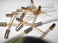
Well these are military spec AC187 (gold pin) and the lowest one had an hfe of 117 and the highest was 387 these are accurate measurements.
I did these measurements with highly precise Philips measurement equipment and i did not beleave it myself either at first.
until i checked these measurements with normal modern silicon transistors, and the measurement equipment was accurate.
I know that an average germanium transistor has an hfe between 30 and 100 or so.
But according the datasheets these AC187 transistors should have an hfe between 100 and 500 so this is normal for these types.
But could someone specify if this configuration is possible??
I appreciate the comments but i still dont have an concreet answer on my
question of the bc179-ac178 sziklai combi is possible because of the difference in base-emitter voltage.
I am an retro freek so that is why i use all these ancient almost forgotten components but i am 22 years old so this is before my time and i need some advice from some of you people who actually saw these things new in store
And i respect the level of knowedge of the people here and i have asked this question to everybody i know but they couldn't answer it.
So please explain it in a relatively simple way, this would help me alot.
Thanks guys.
That spread sounds about right. Even if you match HFE with a meter
at very low currents and room temp, hot devices might be different.
I measured a similar spread in PNP batch from which I cherry picked
my matched sets (I chose 73Beta, cause that allowed for the most
complimetary pairs with the scarce few NPN's I had to choose from.)
The Aleph Pair depends mostly upon VBE threshold (about 0.25V),
and doesn't care too much that Beta could/will be a random spec.
It also shores up unknown MOSFET VGS threshold, which could be
anything from +3V to +9V. The pair now behaves as-if a depletion
mode MOSFET with a dependable -0.25V Germanium drop threshold.
The Germanium is definitely doing something useful!
And I think it holds the power dissipation of the Germainium nearly
constant, so you aren't gonna see wild thermals...
Last edited:
At this moment I am looking at a 35 ish year old Goodmans 3000 receiver this uses Silicon drivers with Germanium output devices in a quasi complimentary output stage this stilll works very well
Also around 1972 i seem to remember a hifi news article for an amplifier with Silicon Drivers and Germanium outputs
Regards Trev
Also around 1972 i seem to remember a hifi news article for an amplifier with Silicon Drivers and Germanium outputs
Regards Trev
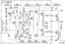
You can use a classical amp schematic like this one.
Only minor adaptations in the resistors values are required to make it operate with germaniums:
You can replace Q1, Q2 and Q6 with your AC187s (all attached to the heatsink).
R10 will have to be increased to get a proper quiescent current, say 10mA.
You can use a fixed 10K in series with a 22K adjustable.
Be sure that the adjustable is set at 0 ohm before you power up!
With no signal, you increase slowly the resistance until you get 5mV DC across R1.
R13 has to be adjusted according to the power supply voltage. You can also use a fixed 10K + 22K adj.
It has to be adjusted so that the (+) of C2 sits exactly at half the power supply voltage (9V in this case).
With the indicated values, the amplifier is theoretically capable of giving 6W into 4ohm (@ 0.30% THD).
Probably a bit over the top for the AC187s.
Other transistors can be any small signal silicons.
Attachments
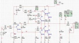
Yes i already designed a circuit myself in multisim before. (see the picture)
But i only needed to know if the silicon germanium comination was possible.
Note that the transistors in the circuit are not the correct types this will be the AC187 transistors of course.
and the first pnp transistor will be a BC179b and i allready found goog PnP Germanium transistors so the output stage will be fully germanium now
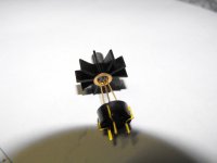
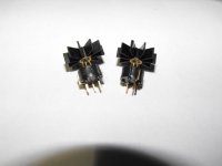
But thanks guys, i also attached some pictures of the devices
Good old stuff right???
But i only needed to know if the silicon germanium comination was possible.
Note that the transistors in the circuit are not the correct types this will be the AC187 transistors of course.
and the first pnp transistor will be a BC179b and i allready found goog PnP Germanium transistors so the output stage will be fully germanium now
But thanks guys, i also attached some pictures of the devices
Good old stuff right???
Attachments
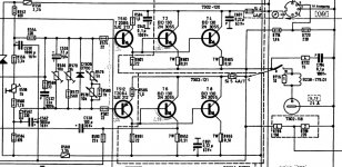
In the case of the Grundig, it is understandable, because they have a balancing role for the two transistors in //.
But in the case of the Sansui, the lower one is practically useless from a T° stabilization perspective.
One might argue that it helps symetrizing the output stage, but this kind of quasi is hopelessely asymetrical anyway, and the effect of the resistor is marginal.
PS
And in fact, placing the resistor there destroys the symetry of the global, composite transistor, which is much worse: I just checked on my sim, when i put the resistor in series with Q2, the 2nd harmonic distorsion shoots from 0.17% to 0.61%.
This settles the case.
If you can measure distorsion on your simulator, you can try both options.
Last edited:
Ok now i am confused does anybody else have an opinion about the placement of these emitter resistors
i have seen this is so many amps in this way so please can somebody rectify this issue and my simulator gave me a distortion of 0.03% at 300MW output
Haven't tried to reverse the resistor yet because i am not at home right now.
i have seen this is so many amps in this way so please can somebody rectify this issue and my simulator gave me a distortion of 0.03% at 300MW output
Haven't tried to reverse the resistor yet because i am not at home right now.
- Status
- This old topic is closed. If you want to reopen this topic, contact a moderator using the "Report Post" button.
- Home
- Amplifiers
- Solid State
- Germanium and silicium transistor in darlington ro sziklai