The last pic that elvee posted is the way i always connect a quasi complimentary output stage. I have seen power transistors explode when connected any other way. The actual output transistor (when connected as elvee shows) is in a local feedback loop created by the driver, the whole thing is under much better control ")
Ok now i am confused does anybody else have an opinion about the placement of these emitter resistors
I have an opinion or three, if you want to be really confused....
Last edited:
I love confusion. Don't keep us in suspense.I have an opinion or three, if you want to be really confused....
Captain A:
You should also try at higher power/lower loads: it will reveal other types of artefacts.
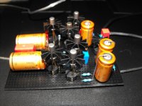
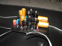
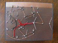
Got one channel working perfectly
Sounds fine with minor adjustments will do a scope adjustment tomorrow.
Lets build a exact copy for the next channel.
and then a 12 volt discrete regulator with the same AC187 transistor
Here some pics
Sounds fine with minor adjustments will do a scope adjustment tomorrow.
Lets build a exact copy for the next channel.
and then a 12 volt discrete regulator with the same AC187 transistor
Here some pics
Attachments
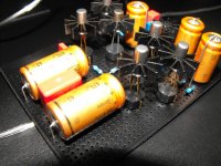
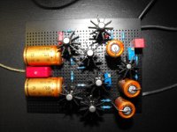
Nice job Captain. It takes me back 25 or 30 years....
Some ideas for further improvements:
Only Q3 and Q5 require a heatsink, and there is still room enough at the top of the case to attach a second cooling clip.
Q1 should preferably be in thermal contact with Q3 and Q5, or alternatively with Q3 or Q5.
When electrolytics stand on their positive end, there is no risk of short-circuit between the positive wire and the can.
A regulated supply will bring little improvement, if any, and if it is not perfect, it might even make things worse. A big fat filter cap is all that is needed.
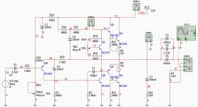
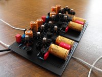
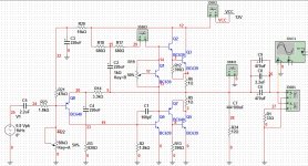
Final
Final schematic and second channel
Everything works fine
it sounds very soft.
I have heard many headphone amps in my life (worked in a theatre) and this one sounds so soft it is almost like the ultimate wooly warm sound.
No hiss or hum problems at all (even with germanium transistors)
well overall gain is exactly 4 so i didnt expect much instability.
it doesnt oscillate at any sircumstances.
and there is lots of power here DAMN!!!!!
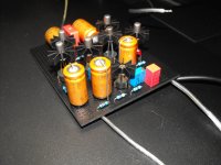
pics below
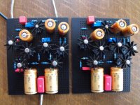
Final schematic and second channel
Everything works fine
it sounds very soft.
I have heard many headphone amps in my life (worked in a theatre) and this one sounds so soft it is almost like the ultimate wooly warm sound.
No hiss or hum problems at all (even with germanium transistors)
well overall gain is exactly 4 so i didnt expect much instability.
it doesnt oscillate at any sircumstances.
and there is lots of power here DAMN!!!!!
pics below
Attachments
- Status
- This old topic is closed. If you want to reopen this topic, contact a moderator using the "Report Post" button.
- Home
- Amplifiers
- Solid State
- Germanium and silicium transistor in darlington ro sziklai