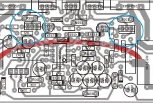
The TO-220’s are needed in the driver positions (on heat sinks). MJE340/350 are fine for VAS (blue circles) although it in NOT incorrect to substitute TO-220’s there - electrically. They just require being flipped the other way on the board IF the original layout is used and the emitter and base resistors for them are where they are supposed to be. Post 3599 shows the TO-220’s non flipped, but the 100 and 1.5 resistors swapped to keep the right values on the emitter and base. This would be ok if the layout was altered to make sure the TO-92’s are driving the bases (And not the emitters). If they are NOT, this needs to be rectified. I can’t see the bottom traces to be sure. The PCB looks entirely homemade, and the layout may or may not be original. If one can hope masood knows what he’s doing. I give it 50/50, though, I’ve seen bonehead mistakes done building these things.
My pcb is differ lookPlease look again MJE340 and MJE350
Attachments
sorry I'm new here so what A, B And Pro connectors for?B500 based on schematics of H900, but in AB class.
Power supply +/-90Vmax.
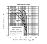
More than an “amendment” to the A500 would be required with that much voltage. +/-80 or +/-85 is the practical upper limit for a normal class AB amp, regardless of how many output pairs and what type you use. Power handing of the transistors themselves falls off with that much voltage. The A900 (class H) can be scaled up to +/-140. Start THERE. The actual amplifier circuit is similar. 10 pairs is about right, maybe 8 with the Motorola/ON types. MJL4281/4302 types would be advisable, although usually 250V types will work (220V or more needed). Full voltage capability (300V) is needed in the front end, however, since that runs at full rail all the time - MJE15034/5 should be used. The rail switching transistors would also need beefing/paralleling. And you will need the quad rails. Easiest way to do that is use two transformers. Two 50-0-50’s in the 1 to 1.5kVA range, off the shelf, are far less money than some custom quad-wound 2KVA+ monster. And probably fits in the chassis better.
Personally, at that kind of voltage/current, I would move to an EF3 output stage, with the driver being the same as one of the outputs. Even the A500, at normal voltage, will benefit from this. I know these designs already use a beta-enhanced VAS that is capable of going into class B when a lot of drive is required, but so do all of mine. I find that it still sounds better because you can bump the idle bias in the DRIVER stage way up, which tackles the crossover distortion problem. There are just a lot of ways these basic designs can be enhanced - don’t be afraid to experiment once you’ve gotten a firm grip on the fundamentals.
Personally, at that kind of voltage/current, I would move to an EF3 output stage, with the driver being the same as one of the outputs. Even the A500, at normal voltage, will benefit from this. I know these designs already use a beta-enhanced VAS that is capable of going into class B when a lot of drive is required, but so do all of mine. I find that it still sounds better because you can bump the idle bias in the DRIVER stage way up, which tackles the crossover distortion problem. There are just a lot of ways these basic designs can be enhanced - don’t be afraid to experiment once you’ve gotten a firm grip on the fundamentals.
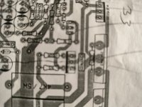
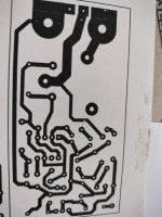
Please share it's bottom pdf.thankshi.i try to find b500 gerber files but i think no one want to share it. i draw it on proteus. if any good of you check it and if all its ok i will share gerber files.
note: i make a little place for coolers so its a little bit bigger then orginal pcb.
thank you.

- Home
- Amplifiers
- Solid State
- 500W PA amplifier with Limiter