Well, it is different to get the idea from someone who has worked it all out, knows which situation it applies in and why. Still, I think a multi-pole RC filter would work better. It would be nice to see the original explanation though.
I always work on the dominant distortion mechanism first, and LTP source impedance balance almost always falls close to last on that list. I usually don't bother because I expect the input pot to disrupt the balance. If I wanted to I would buffer the input so I could control the impedances, but so far it's been a very low priority. After all, any null is only as good as the component matching. So you've got 4 5% resistors (20% total potential mismatch just from individual tolerances) and you've got 2 transistor junctions and you have no idea how well they may be matched. It's probably better to use a cascode.
I always work on the dominant distortion mechanism first, and LTP source impedance balance almost always falls close to last on that list. I usually don't bother because I expect the input pot to disrupt the balance. If I wanted to I would buffer the input so I could control the impedances, but so far it's been a very low priority. After all, any null is only as good as the component matching. So you've got 4 5% resistors (20% total potential mismatch just from individual tolerances) and you've got 2 transistor junctions and you have no idea how well they may be matched. It's probably better to use a cascode.
It would be nice to see the original explanation though.
If I can remember where I found that, I'll post back, but at the moment it's gone from my nugget.
After all, any null is only as good as the component matching.
Personally I think no amp should be built without having tested and matched as many parts as possible. And for resistors, whenever possible use the 1% or better.
It's probably better to use a cascode.
Instead of the sziklai pairs?
btw: I was looking into your cfp ripple eater thingy (not on this design), and I couldn't get the effect I was expecting, as the ripples are mostly passing through. I may be missing something, but what? I don't need and don't want to regulate in that design, but I'd like to reduce the ripples as much as possible. I have a good 70mV peak to peak of ripples passing through there, even through that cfp ripple eater, and a whole lot more when using the resistor in parallel with the cap. I don't want too much of a drop of voltage either, the rails are only 35V and with a psu sagging, every volt is precious.
1: The drivers are probably working like mad to satisfy the enormous capacitance of the outputs, in addition to the high currents through the nonlinear Cob of the Vas and drivers. These are most likely the cause of 3rd harmonic distortion, if it is more than you would expect normally from loading the outputs.
2: The LTP source impedance imbalance depending on which side is lower can add a 2nd harmonic which may add to or cancel the 2nd harmonic from the proceeding stages. The Sziklai LTP virtually eliminates the load-dependent contribution of Ib to distortion, so it seems there are less distortion mechanisms that would cause H2 altogether.
I've stopped considering THD changes less than at least 6db significant, because less than that and the cause is often simply the stages' individual harmonics canceling in some way. So one or two harmonics are lower but the rest are the same, which the THD meter won't tell you. Often this cancellation only occurs at specific operating conditions and signal levels and device matching so it's a bad idea to depend on it.
Instead of the sziklai pairs?
They don't improve CMRR and PSRR like a cascode does, although they do lower distortion simply because they increase the LTP gain.
btw: I was looking into your cfp ripple eater thingy (not on this design), and I couldn't get the effect I was expecting, as the ripples are mostly passing through. I may be missing something, but what? I don't need and don't want to regulate in that design, but I'd like to reduce the ripples as much as possible. I have a good 70mV peak to peak of ripples passing through there, even through that cfp ripple eater, and a whole lot more when using the resistor in parallel with the cap. I don't want too much of a drop of voltage either, the rails are only 35V and with a psu sagging, every volt is precious.
It's hard to say without being able to look at how you did it.
1: The drivers are probably working like mad to satisfy the enormous capacitance of the outputs, in addition to the high currents through the nonlinear Cob of the Vas and drivers. These are most likely the cause of 3rd harmonic distortion, if it is more than you would expect normally from loading the outputs.
The tip35 datasheets that I have don't provide any cob data, but I suspect it's significant. Perhaps adding a speed up cap on the drivers' resistance might be a good idea.
2: The LTP source impedance imbalance depending on which side is lower can add a 2nd harmonic which may add to or cancel the 2nd harmonic from the proceeding stages. The Sziklai LTP virtually eliminates the load-dependent contribution of Ib to distortion, so it seems there are less distortion mechanisms that would cause H2 altogether.
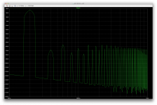
So this would in part explain why that h2 was a little lower than the h3 on that fft at 20k.
I would think a cascode would not bring as big of an improvement on thd as the sziklai pair does, and trying to use both would probably be overkill and may even cause more issues and lower the benefits instead.
It's hard to say without being able to look at how you did it.
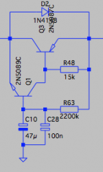
This is probably not the appropriate thread for it. I'm attaching a screenshot of what I have now, after removing that resistor in parallel with the cap and I also tried various values for the resistor leading to it.
One issue that I have with it is the time it takes to charge and settle. But I couldn't get a quiet rail.
Attachments
Wow, that's almost nothing like my circuit. Why don't you simulate the Kmultiplier in my signature and start from that? You'll learn what you did wrong.
Ok I'll take an other look there.
I tried several things. Nothing worked right so far.
I was looking at your post #16 on the thread http://www.diyaudio.com/forums/power-supplies/177516-keantokens-cfp-cap-multiplier.html
I wanted to keep the number of parts low, but that seems like not really possible.
That was long before I had tweaked the best version out. You can keep it simple if you're designing for a specific application, once you know what things make the circuit as good as it is.
Yes, I see many different versions.
I wouldn't want to use TO220 parts, at the most TO126, but I don't even think it's necessary for what I use them for, as it's only for the front ends of amps that need 20-30mA, rarely more.
I'll do some testing with what you have on your page. But I'll be looking for smaller transistors than TO220 cases.
For the smaller one, perhaps the mpsa18 is a good one, however if I remember right, that one doesn't have a complementary, so that would make the negative side different because of using a different one.
OK, thank you for the reply. I didn't do a very good job at clarifying what I was referring to, but what I meant was that the first Apex schematics in this thread look like they were pulled right from an early MX series Yamaha amplifier. The resemblence is so pronounced, that it's uncanny. In fact, with the exception of some obvious errors in Apex's drawing and the choice of alternate devices, they are the same. What struck me was that the patent for that particular discrete transconductance driver arrangment was owned by Yamaha in the 70's through the 90's. I'm surprised others hadn't taken notice of this, as some of the Japanese company's designs have been cloned by other makers over the years.It's the apex ax11. As is. Hardly changed, except for the different models because I couldn't get the exact ones called on by the schematic and also I added a resistor in the bias spreader to reduce the idle as it is high with the values on the schematic.
One added difference lately is to lower the miller caps from 330p to 33p, which changes things a lot, as the sine wave was ugly at 20khz.
Last edited:
Hi kouiky, have you read the whole thread,
The ax14 is similar to Yamaha AX series,
This has been mentioned many times.
But thanks to Apexaudio the rather nice yamaha amp has
Been made DIY for the community.
I have built the AX14 not the AX11 yet and I'm very happy with it.
Regards
The ax14 is similar to Yamaha AX series,
This has been mentioned many times.
But thanks to Apexaudio the rather nice yamaha amp has
Been made DIY for the community.
I have built the AX14 not the AX11 yet and I'm very happy with it.
Regards
The thread is pretty long, so I didn't go page for page. What happened was I browsing and the design popped out like a hammered thumb as one of a kind. I immidiately yanked the early patent, and there it was. Looks like I guessed right. Some of the AX series share similar topologies to the MX separates, and that driver stage was unmistakable as the early Yamaha patented SEPP driver stage. I was aware it had been cloned and used in some higher end amps from some...ahem certain designers. I'm surprised that Apex also used it because it's off the radar, despite being a fantastic design.
Last edited:
hello apex sir Which amp can drive 250watts 4ohm heavy subwoofer
i have made 5@ LM3886 and searching for subwoofer amplifier to drive my hi power 12'' subwoofer
APEX HV23 or APEX HV350,easy and with a lot of reserve power!
APEX HV23 or APEX HV350,easy and with a lot of reserve power!
Tq u for your suggestions sir can u give circuit, pcb and testing files
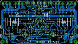
Has some one already build this layout from mister Alex MM ?
I use this PCB. Now I'm listening to it and I'm pleased of what I hear. It works fine , even if it has no dc servo. Sound is real good for me. Much better then my english...
- Home
- Amplifiers
- Solid State
- 100W Ultimate Fidelity Amplifier