I need help buying a good amp. My budget is about 1000 dollars. But I need to know Amplifier measurements that determine amplifier quality
We all know RMS power capacity, dynamic power capacity, frequency response, current capacity, output impedence and distortion are important measures.
What else is important in an amplifier. How can we tell an amplifier is of high quality based on hard engineering measurements.
I know that auditioning is needed to detect finer points of amplifier design. But here I am looking for things that can be objectively measured.
What can we measure in NAD and Parasound that is not available in Yamaha, Denon or Onkyo.
I have a question, that I like to be answered with consistency.
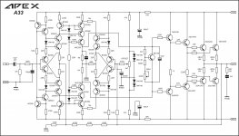
As what was posted from the very beginning, the OT stated 120W into 4 ohm load. I noticed the 2SC5200 swamping resistors are 0.33 ohm 5W, lets get into math.
Lets determine the output current with 120W output power and 4 ohm load.
P = (I^2)*(R) so,
I = sqrt(120/4) = 5.47A
Now lets get the resistor's dissipated power using same formula.
P = (I^2)*(R) = (5.47*5.47)*(0.33) = 9.9W
A staggering 9.9W!
I design amplifiers so they do not blow up whenever cases except user's stupidity so that is why I asked. Why was it rated for just 5W? I beg for answers.")
Ken
As what was posted from the very beginning, the OT stated 120W into 4 ohm load. I noticed the 2SC5200 swamping resistors are 0.33 ohm 5W, lets get into math.
Lets determine the output current with 120W output power and 4 ohm load.
P = (I^2)*(R) so,
I = sqrt(120/4) = 5.47A
Now lets get the resistor's dissipated power using same formula.
P = (I^2)*(R) = (5.47*5.47)*(0.33) = 9.9W
A staggering 9.9W!
I design amplifiers so they do not blow up whenever cases except user's stupidity so that is why I asked. Why was it rated for just 5W? I beg for answers.
Ken
Last edited:
It also goes without wire
regards Olaf
Which software you are using for designing this PCB? Professional look
You speak of average power that would be half of the max power which is 4.95W. I will research more about this
No power would be 2,5W max...
The emitter resistor operates at a duty cycle of 100% for the continuous bias current.
At maximum power the duty cycle has reduced to 50%
Therefore the average dissipated power is 50% of the calculated value using the output current as the basis.
That resistor will heat up rapidly during maximum power testing and even more during SQ Wave testing.
During music reproduction where the average output is ~ 1% of the maximum output the resistor will not get warm.
Distortion measurement is a very good method of determining if the second and third and etc, amplifier has a "fault" in the assembly. Very simple wiring errors can and will give an enormous increase in measured distortion.Amplifier measurement that determine amplifier quality
We all know RMS power capacity, dynamic power capacity, frequency response, current capacity, output impedence and distortion are important measures.
.............
Distortion is not a good method of assessing audio performance.
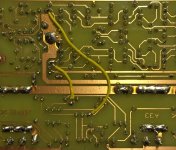
as usually,great job Olaf! just great!
i can see that you are using that yellow capton tape,and i am curious what are it´s characteristics? how does it transfer heat-can you measure temperature of transistor and heatsink bellow it? is it 3M tape or...
Hi, thanks for the kind words.
I use the Kapton film for quite some time. Was discussed here in the forum (I think still4given used it at first, but not sure). I have never made measurements, but also any bad experiences. In general, the very good thermal conductivity of Kapton is known. Mine comes from ebay, 30m long, 50mm wide for about 10 euros, labeled 3M. I am very satisfied. And much cheaper then silicon-foil.
regards Olaf
Last edited:
Just finished to layout PCB for A33 amplifier ,all OT in line ,not tested yet
Olaf ,nice to hear it's working ......
Regards,Alex
Hi Alex, looks great as usual
Much success in the test. I look forward to your opinion on the sound. I have yet to hear a little.
Max. voltage - please ask Mile. I want to drive the amp with +-50VDC. Will check it next days.
regards Olaf
Hi Alex, looks great as usual
Much success in the test. I look forward to your opinion on the sound. I have yet to hear a little.
Max. voltage - please ask Mile. I want to drive the amp with +-50VDC. Will check it next days.
regards Olaf
Use +/-55V max.
Regards
A33 Layout
Hi, here are the layout-files for the A33.
Please do not forget the wires between the points marked as A-A, B-B.
Much success and have fun.
regards Olaf
Hi, here are the layout-files for the A33.
Please do not forget the wires between the points marked as A-A, B-B.
Much success and have fun.
regards Olaf
Attachments
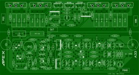
I use Sprint Layout 6.0 fromWhich software you are using for designing this PCB? Professional look
Sprint-Layout
It is very easy to learn and not so expensive.
regards Olaf
I used the schematic as published by apexaudio.Does The sprint have schematic capture..?? Or how is the input interface.??
Only difference is replacing driver 2SC4793/2SA1837 with 2SC2238/2SA968.
Attachments
Hi, here are the layout-files for the A33.
Please do not forget the wires between the points marked as A-A, B-B.
Much success and have fun.
regards Olaf
Thanks for the files, can you compare sound A23 vs A33?
Regards
Oh, I see.What I meant, was not the actual schematic, but how you put it into sprint, can it capture schematics from spice..?
That ist the greatest disadvantage of Sprint. It ist only painting for PCB. No Connection between schematic and layout
.I've only heard A33 a couple of minutes. The first impression is, I think, they are very similar in the highs and mids and A33 is a bit stronger in Bass. But give me more time.Thanks for the files, can you compare sound A23 vs A33?
Regards
regards Olaf
- Home
- Amplifiers
- Solid State
- 100W Ultimate Fidelity Amplifier