A9 vs. BG1 by Borys from FET-hex explendit amplifier thread .BG1 has a little more bass, just a little more deeper ,the rest is almost the same.Both plays very well,but for me the best sound has the AX14 with 2 pairs output. A9 ,BG1,AX11,AX14 are all very good and all are worth to try.
Regards
zoky2
Regards
zoky2
Attachments

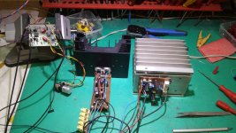
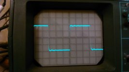
today i did some measurement: 15kHz square 2Vp (4Vpp) output,slightly inductive (60uH) active 8Ohm load with and without 470nF in paralell. osciloscope probe was connected to PCB output and PCB-GND,here are the results:
Attachments
today i did some measurement: 15kHz square 2Vp (4Vpp) output,slightly inductive (60uH) active 8Ohm load with and without 470nF in paralell. osciloscope probe was connected to PCB output and PCB-GND,here are the results:
Nice measurements, thanks.
Regards
A9 vs. BG1 by Borys from FET-hex explendit amplifier thread .BG1 has a little more bass, just a little more deeper ,the rest is almost the same.Both plays very well,but for me the best sound has the AX14 with 2 pairs output. A9 ,BG1,AX11,AX14 are all very good and all are worth to try.
Regards
zoky2
Thanks for report,
Regards
i am still waiting for still4given to recover where was the mistake...
any progres?
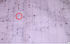
Terry uses 2 resistors for the 220k in below schematic. If the value is 220k+220k=440k the bias will of course be higher than expected. If 100k+100k=200k, that's lower than specified but is fine.
Attachments
Terry uses 2 resistors for the 220k in below schematic. If the value is 220k+220k=440k the bias will of course be higher than expected. If 100k+100k=200k, that's lower than specified but is fine.
Yes but they are two 110k in series.
BTW I found the issue with my boards. I had BD550 in for both of the input transistors. Works fine now. I will post some scope shots a little later.
Yes but they are two 110k in series.
BTW I found the issue with my boards. I had BD550 in for both of the input transistors. Works fine now. I will post some scope shots a little later.
you mean bC550?
it really doesn´t matter now,it is important that you have a working amplifier! i told you what mistakes i do mostly,those are often made mistakes : mis-placed resistor or transistor,unwanted copper or soldier connection on PCB...
you mean bC550?
it really doesn´t matter now,it is important that you have a working amplifier! i told you what mistakes i do mostly,those are often made mistakes : mis-placed resistor or transistor,unwanted copper or soldier connection on PCB...
Yes, sorry for the typo.
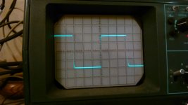
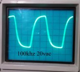
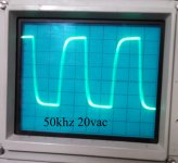
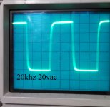
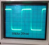
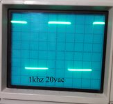
I misread it on the board. Should have noticed they were npn, pnp on the schematic. Here are some shots of square waves. 20vac output. 1khz. 10khz, 20khz, 50khz and 100khz. Probe ahead of the zobel.
Attachments
i tested A23 with 8r 60uH 470nF load,with 100r in feedback (between 10uF and GND on schematic) and with 82r instead 100r. i replaced 100r to 82r to get higher amplifying ratio. picture of a first test was shown by Mile APEX a few pages of this thread earlier,and a picture of a second test was shown in my post one page earlier. second picture with 82r in feedback shows that amplifier has lower ringing in a square wave and it gets it earlier to a flat horisontal line.
i did a 1,5 15 150 kHz 8r 60uH square signal test with a few more searious amplifiers,and A23 was not the best among them and was not the worst.
than i did the same test but on 8r 60uH 470nF with all the same amplifiers, and A23 has shown a best recovery time from ringing to a flat horisontal line.
that shows it's ability to deal with complicated loads,and that shows something...
(all measurings were done with osciloscope probe at amplifier output and GND connections)
A33 alive!
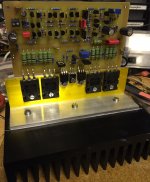
Hi, A33 alive!
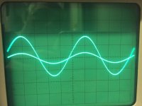
In the test environment it runs with + -36V. Offset is good and lies between -20mV and + 20mV, the trimmer is very sensitive, but can adjusted nearly to null. Bias is adjustable between 0 and 500 mA. I have it set to 150mA for initial testing. Sine wave looks very good (picture is 20kHz). Input is 0.5V / div, Out is 2V / div. Because I have no more time today, more tests will follow tomorrow afternoon. The sound is very clear and neutral, good deep bass, transparent highs. For a first test, a very beautiful sound.
regards Olaf
Thank you Mile again!
Hi, A33 alive!
In the test environment it runs with + -36V. Offset is good and lies between -20mV and + 20mV, the trimmer is very sensitive, but can adjusted nearly to null. Bias is adjustable between 0 and 500 mA. I have it set to 150mA for initial testing. Sine wave looks very good (picture is 20kHz). Input is 0.5V / div, Out is 2V / div. Because I have no more time today, more tests will follow tomorrow afternoon. The sound is very clear and neutral, good deep bass, transparent highs. For a first test, a very beautiful sound.
regards Olaf
Thank you Mile again!
Attachments
Last edited:
Hi, A33 alive!
In the test environment it runs with + -36V. Offset is good and lies between -20mV and + 20mV, the trimmer is very sensitive, but can adjusted nearly to null. Bias is adjustable between 0 and 500 mA. I have it set to 150mA for initial testing. Sine wave looks very good (picture is 20kHz). Input is 0.5V / div, Out is 2V / div. Because I have no more time today, more tests will follow tomorrow afternoon. The sound is very clear and neutral, good deep bass, transparent highs. For a first test, a very beautiful sound.
regards Olaf
Thank you Mile again!
No, thank you, you made A33 alive,
Regards
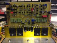
PCB rev 1.0 --- A33 amplifier
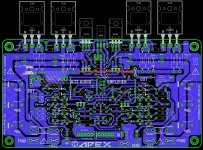
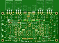
Just finished to layout PCB for A33 amplifier ,all OT in line ,not tested yet")
Olaf ,nice to hear it's working ...... Please, tel me ,voltage range for A23 and A33 amplifier ,thanks .
Regards,Alex
Just finished to layout PCB for A33 amplifier ,all OT in line ,not tested yet
Olaf ,nice to hear it's working ......
Please, tel me ,voltage range for A23 and A33 amplifier ,thanks . Regards,Alex
Attachments
Last edited:
Just finished to layout PCB for A33 amplifier ,all OT in line ,not tested yet
Olaf ,nice to hear it's working ......
Regards,Alex
Nice pcb,
Regards
Amplifier measurement that determine amplifier quality
We all know RMS power capacity, dynamic power capacity, frequency response, current capacity, output impedence and distortion are important measures.
What else is important in an amplifier. How can we tell an amplifier is of high quality based on hard engineering measurements.
I know that auditioning is needed to detect finer points of amplifier design. But here I am looking for things that can be objectively measured.
What can we measure in NAD and Parasound that is not available in Yamaha, Denon or Onkyo.
- Home
- Amplifiers
- Solid State
- 100W Ultimate Fidelity Amplifier