Just rotate 180deg all TO92 transistors on your pcb
Yes you should double check all CBE connections on all your to92 transistors.
In my nature is that if someone is telling me DO NOT do it, this becomes first thing I am going to do. So I have soldered current mirror to the LTP, I just added 10pF in NFB for safety (all is stable with cap load), the top octave became more delicate and I am happy with it. The offset is 6mV and remains stable in fuction of temperature. Performance looks ok.
I do not know if that kind of front of the amp is technically ok but it survived 2h of playing the music anyway, I did not checked the output bias stability --> will do that tomorrow.
VAS current on your amp is to low (about 3mA)
apexaudio
Thanks for response.
I have measured bias and:
-input is 2,5mA (total)
-VAS is 7,3mA (I do not know If it is enough but it is cool enough to fitt to92 large pack toshibas there)
-outputs biased at 100mA per device
I am building my next amp with EF3 output stage and j-fet input but still can not decide which way to go, ''Pure Push-Pull'' or classic as ax14 (VAS with courrent source).
Maybe you can advise me about temperature compensation in EF3,
I am going to use 2 pairs of output transistors and can I use single BD139-16 (or maybe some of super-beta transistor ) for temperature compensation ? Or use double transistor compensation like NPN - PNP style ?
Thanks
Attachments
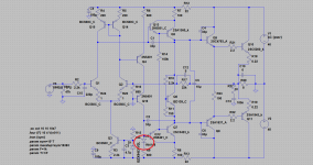
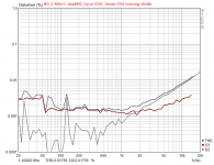
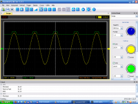
Just for curiosity I have connected diode to lower vas transistor (didnt adjust the rest of the currents yet). Bellow just for compare 15Vp-p at 8R load.
The phase shift transistor is only 275uA now it is bit too low, circuit need some adjustment (I try to test it later on). BTW the output transistor bias is very stable - so thumbs up.
It looks like the first prototype had more 2nd harmonic and very low 3rd one.
So prapobly better stick with the 2nd one.
Attachments
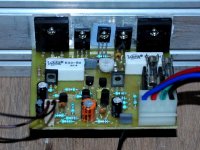
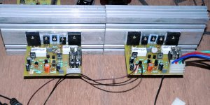
Hi again,Just rotate 180deg all TO92 transistors on your pcb
Many thanks Mr. Mile, the amplifier is worked ok now.
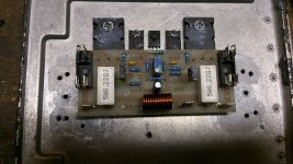
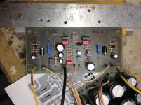
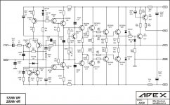
This is corrected placement of all TO92 transistors if you are use 2N5551 and 2N5401 (see attachment)
My power supplies are +/-42V and +/-56V. You can see the output signal vs power supply on a picture 2 below:
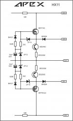
The resistors in commutator circuit with value 2k2 are very hot and I think their value should be change with 10k or replaced with 1W resistor instead 0.25W.
The commutator circuit is attached below
Attachments
")
i have 2 x 24-0-24 5 amper traffo can i use it for 2 ax11?
https://www.facebook.com/pages/Vish...4249738966975?ref=stream&hc_location=timeline
https://www.facebook.com/pages/Vish...4249738966975?ref=stream&hc_location=timeline
apexaudio
Maybe you can advise me about temperature compensation in EF3,
I am going to use 2 pairs of output transistors and can I use single BD139-16 (or maybe some of super-beta transistor ) for temperature compensation ? Or use double transistor compensation like NPN - PNP style ?
Thanks
I built 3EF OPS base on Ostripper design (not exactly same but construction is same). Please see http://www.diyaudio.com/forums/solid-state/248105-slewmaster-cfa-vs-vfa-rumble.html
sorry for mistake (-60ma) its -60 mv
What transistor did you use in Q1 & Q2?
2n5401
Just make sure your TO-92 transistor (specially on first stage) is made from the same manufacturer otherwise if they are the same value but different manufacturer will result this high DC offset.
I would not use low power smd resistors for the base stoppers of the output devices. These can take quite a pulse during rare moments.
R11 may require quite high dissipation capability.
Check the dissipations of all your components and compare to the maximum for that device.
R11 may require quite high dissipation capability.
Check the dissipations of all your components and compare to the maximum for that device.
- Home
- Amplifiers
- Solid State
- 100W Ultimate Fidelity Amplifier