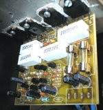
BIAS 100mA
THD< 0,05%; TIM< 0,07%
F 20Hz-20kHz +/-0,1dB; 2Hz-250kHz +0/-3dB
Damping >200
S/N >108dB
I am afraid these figures are all but meaningless unless the conditions they are taken under are quoted as well.
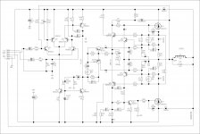
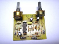
If you interested about PCB, I take time to design new version with over current limiter.I am interested in your amplifier can you please give furthere details
regards Trev
Really? I had assumed BF871's purpose was already to fix one cold emitter's
voltage drop across the pair of .22R by stealing bias current away from the
driving pair. That alone should assure a runaway-less output current that is
pretty much forced to follow class A rule of I1+I2=Constant. But this might
only happen when there is far more idle current dialed-in than desirable.
If you bias less than the full linear class A rule, perhaps AB by mosfet square
law rule??? Then that limiter transistor would be turned off most of the time.
I'm not sure sonic goodness of letting a transistor sometimes turn completely
off. If its always off, thats OK. Its still there from a safety standpoint.
I think you can get close to AB efficiency without ever turning anything off.
The class I speak of is Hyperbolic A. If you exchange each of those 0.22R for
0.1R + MBR745 Schottky in series. And bias CC up high enough that the limiter
is always in effect as a shunt regulator.
Holding voltage drop across the sensing resistors and Schottkys to constant.
Will give back a very square law curve, following rule of cold Schottky Diodes
in the sensing totem, rather than square laws of the MOSFETs. Neato! Cause
now nothing ever turns off, nor runs away with hot output devices.
The hyperbolic A curves are close to AB. You might set idle current ~600mA?
I can draw a picture tomorrow if it helps. We aren't talking bout mods severe
enough to need a new layout if one exists (I'm assuming it does)... Just two
diodes in series with slightly different choice of sense resistors.
Last edited:
Yeah, sorta like that. You see Yorkville Q9+Q10 sensing a similar function.
I don't think it needs to be that complex. I see upper half bootstraped like
Aleph, Lower half not needin' bootstraps cause its Quasi. And the whole
ball of crossover correction driven from between emitters like an Allison.
How close will yours pull to the upper rail without a bootstrap or separate
supply voltage for the gate drive?
how many waats rms ca give it? can I use it as subwoofer amp plz give me detailsThis two old modules (about 20 years) same circuit without curent limit, with BF422/BF433 and BUZ21x4 stil in use work on +/- 36 DC.
About 7V, but simplicity for DIY is priority.
This is what happens when I try to "fix" something what ain't broke.
At first, I couldn't get my mod to behave as hoped/described above.
But after screwin' round several hours, I come up with this instead???
Its almost a Visch glitchless class B crossing, plus a small pair of
constant currents loads that prevent anything but Schottkys from
actually turning off. Yes, like B , yet somehow not B , what???
I think it may be thermally stable, though not for AB usual reasons.
Except for those constant current, its trying very hard to shut off.
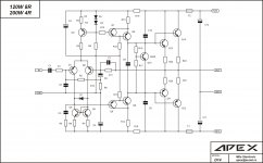
I think you can still see a lot of Apex's original design and topology
deserving credit. Certainly no longer anything one could hope to
patch into an existing layout. I won't distract this thread further
with this tangent. I just thought you might want to see this crazy
ideas you inspire drawing till 2:57AM on a night before a workday.
Those currents were plotted at the verge of clipping at 22KHz.
They look even nicer at 1KHz, but that would be cheating...
And it will tolerate a little clipping without goin' banannas.
Attachments
Last edited:
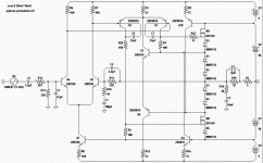
For all aplication especialy for subwoofer I recomend you Kelvin amplifier without VI limiter. You also need active X-over for subwoofer.how many waats rms ca give it? can I use it as subwoofer amp plz give me details
Attachments
For all aplication especialy for subwoofer I recomend you Kelvin amplifier without VI limiter. You also need active X-over for subwoofer.
Mile, C3 and R5 must be removed, otherwise the circuit will
have a hard rail sticking when the amps clips...
Stability should be settled with a less destructive
(for tweeters) mean..
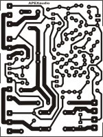
parts list, and PCB layout plz..................For all aplication especialy for subwoofer I recomend you Kelvin amplifier without VI limiter. You also need active X-over for subwoofer.
R1-1kparts list, and PCB layout plz..................
R2,R11-22k
R4,R6,R7,R8,R16-560R
R5,R10,R14,R15,R17,R18,R19-220R
R9,R12,R13-100k
R20,R21,R22,R23-0R33 5W
C1-10uF/25V ELKO
C2-100pF KER
C3-1500pF KER
C4,C5,C11,C12-2,2uF/63V ELKO
C6-100uF/25V ELKO
C7-330pF KER
C9,C10-220pF KER
C8-100nF MKS
D1,D2,D3-1N4148
Q1,Q2,Q3-2N5401
Q4,Q5,Q7-BC547
Q6-BC557
Q8-MJE340
Q9-MJE350
Q10-BD139
Q11,Q12-BDW84D
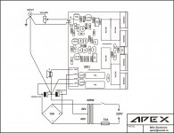
PCB size:62,5x82,5mm
Q13,Q14-BDW83D
Attachments
Wahab, can you send me file with LTspice or Tina-TI simulation. In real world aplication, I have diferent expirience.Mile, C3 and R5 must be removed, otherwise the circuit will
have a hard rail sticking when the amps clips...
Stability should be settled with a less destructive
(for tweeters) mean..
Regards Mile
I hope that we will see functional amp soon.thank you friend
Wahab, can you send me file with LTspice or Tina-TI simulation. In real world aplication, I have diferent expirience.
Regards Mile
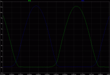
Here a comparison..
Red line is with the RC circuit connected.
Green is the same amp , only the RC circuit is removed.
Anyway, the amp seems to have no need of this circuit
to achieve stability.
Attachments
I will remove RC, and do make some test, thank you Wahab.Here a comparison..
Red line is with the RC circuit connected.
Green is the same amp , only the RC circuit is removed.
Anyway, the amp seems to have no need of this circuit
to achieve stability.
I will remove RC, and do make some test, thank you Wahab.
I forgot to specify that the frequency of sim is 10KHZ.
If you have a scope, it s easy to check in real world
the validity of the simulation.
Please, can you give the results ?
It will be helpfull as a lot of designS use RC circuits related
to the current mirrors.
Thank you by advance, mile..
- Home
- Amplifiers
- Solid State
- 150W MOSFET Amplifier with IRFP250x2