Hi everyone. I have the opportunity to get an old Phase Linear 700B with a blown channel, therefore it is my intention to purchase on eBay a repair kit with all the parts (transistors, dioids, caps) for a complete and symmetrical restoration of the amp. Now, as I would like to use it in my main system, I'm thinking to replace also the output transistors with an interesting upgrade kit from LDX Technologies.
Phase Linear 700 Upgrade and RepairTransistor Kit su eBay.it Other, Vintage Electronics, Electronics
I would like to know your opinions about that. Anyone who already tried that upgrade in his PL? Thanks for your attention.
Phase Linear 700 Upgrade and RepairTransistor Kit su eBay.it Other, Vintage Electronics, Electronics
I would like to know your opinions about that. Anyone who already tried that upgrade in his PL? Thanks for your attention.
Looked at the kit and seriously- 24 power transistors for that price is not out of line for repair parts. I think this guy believes he is trying to do the world a favor with proper matched up devices. Am not saying this will fix an unstable amp or anything like that but for a novice it seems okay.
I first heard of this kit when looking for parts on eBay there was a 700B with this kit installed so I saved the text for reference, here it is -
You are bidding on a Phase Linear 700B audio power amplifier. This amplifier has been fully upgraded with the LDX technologies upgrade kit. It has better performance then when first manufactured.. Cosmetically good and electrically excellent.
The upgrade for this type of amplifier is power matching of the power output structure. Typically it consists of multiple power transistors in parallel with emitter balance resistors to make up for small gain differences in the transistors. The Phase Linear series amplifiers use a triple darlington quasi-complementary configuration which was designed to lower the total harmonic distortion(THD), inter-modulation distortion(IMD), and transient inter-modulation distortion(TIMD). With these configurations, replacing just one or two transistors may make the amplifier function again, but not at it's best performance. At high levels, a-symmetrical clipping may occur because of uneven power sharing. Replacing all power transistors is a better solution but is still not perfect. The reason here is because of high current beta collapse in the output stage of the amplifier. Bob Carver discovered that other amplifiers of the time that he designed the Phase Linear series, used a dual darlington output stage. This configuration had a distortion curve that would rise quickly with an increase in the current in the output transistors. Beta or gain collapse was the cause for this. Bob's triple darlington significantly improved the performance, but you still could not get optimum performance by just replacing the transistors with off the shelf units. To achieve the highest performance requires matching the Beta of both sections of the darlington totem pole.
The original output transistors in the Phase Linear amplifiers where diffused type topology. Although quite rugged, they would limit the high frequency performance of the amplifier. In the kit I designed uses brand new epitaxial topology power transistors which yield significantly better high frequency performance and ruggedness than the original Phase Linear power transistors.
Some power transistor replacements for Phase Linear Amplifiers used early versions of Motorola epitaxial topology transistors (TP9054) and did not have good high collector current gain and proved to be not so robust. I use state of the art epitaxial power transistors and test and match them in the same totem pole configuration test fixture with the same circuitry as in Phase Linear amplifiers. The upper and lower totem poles were independently characterized for beta at 32 amperes collector current and then burned in for 72 hours. They then have a final test and were installed.
The LDX kit uses fully measured matched sets of triple darlington sections which include: 2 NPN predrivers, 2 NPN drivers, and 10 NPN output transistors for the upper half totem pole of both the left and right channels, 2 PNP predrivers, 2 NPN drivers, and 10 NPN output transistors for the lower half totem pole of both the left and right channels, 2 high voltage NPN gain stage transistors, one for left and one for right, 6 heat sinks and mounting hardware sets for the gain stage and pre-driver transistors (a total of 30 new transistors), 28 new TO3 mica insulators for the driver and output transistors. This kit and the transistor sets are unconditionally stable with the Phase Linear 700B. This means that no additional phase compensation capacitors are required, which when used reduce the slew rate of the amplifier and consequently increase the Transient Inter-Modulation Distortion (TIMD). Unlike original transistor replacement and partial transistor replacements, the LDX kit brought this Phase Linear 700B series amplifier to todays state of the art performance! It has better performance then when first manufactured..
Cosmetically good and electrically excellent. With more than 350 Watts per channel into 8 Ohms, this is a great studio monitor or home audio amplifier. LDX upgrade manual included. PayPal preferred. Happy Bidding
Sounds good???
Far as I can tell, he's not supplying any caps or Ge devices.Do you know what value to change the compensation caps to?
Do you know where to buy the germanium devices?
I stand corrected, I was thinking of this seller (qua-co):
PHASE LINEAR 700 OUTPUT TRANSISTOR SET NEW!!! - eBay (item 370328007623 end time Mar-01-10 06:48:20 PST)
PHASE LINEAR 400 700 SERIES II REPAIR KITS NEW!! - eBay (item 280456692225 end time Feb-24-10 14:26:18 PST)
PHASE LINEAR 400 700 SERIES II REPAIR KITS NEW!! - eBay (item 280456692225 end time Feb-24-10 14:26:18 PST)
PHASE LINEAR 400 700 700B 2N1304 2N1305 TRANSISTOR SET - eBay (item 280454786162 end time Feb-20-10 10:05:15 PST)
And I don't know what compensation values he is using (he may sell you a set of service bulletins if you ask).
Last edited:
Do you know what value to change the compensation caps to?
Do you know where to buy the germanium devices?
From what I can tell I'm not sure the compensation caps are required. I realize that they are required for most conversions but this one appears to be different. Here's the parts list..
In this kit you get fully measured matched sets of triple darlington sections which include: 2 NPN predrivers, 2 NPN drivers, and 10 NPN output transistors for the upper half totem pole of both the left and right channels, 2 PNP predrivers, 2 NPN drivers, and 10 NPN output transistors for the lower half totem pole of both the left and right channels, 2 high voltage NPN gain stage transistors, one for left and one for right, 6 heat sinks and mounting hardware sets for the gain stage and pre-driver transistors, 26 new TO3 mica insulators for the driver and output transistors (2 extra just in case), and thermal compound for all transistors. Also included is a 33 page comprehensive instruction manual I have written on removing the old parts and installing the new ones including testing and alignment of the amplifier. This kit works with all board revisions of the Phase Linear 700, 700B, and 700II series and the transistor sets are unconditionally stable in all versions of these amplifiers. This means that no additional phase compensation capacitors are required, which when used reduce the slew rate of the amplifier and consequently increase the Transient Inter-Modulation Distortion (TIMD). Unlike original transistor replacement and partial transistor replacements, my kits will bring your Phase Linear 700 series amplifiers to todays state of the art performance!
In regard to the Germanium transistors I can get them at this time but... I was advised by someone that rebuilds these units to remove them and leave them out... which I have done... and now I'm wondering if that really is the thing to do?
I'm an M.E. not an E.E. but after building a Megasquirt Engine management system for my track car I keep getting deeper into eletronics but I can still get lost real quick!!! Just trying to keep my vintage stereo stuff going...
Thanks
Scott
Working on a dead 400 II (full complimentary output section) right now with the LDX kit in it. In this kit you'll get MJE340/350s for little Qs and MJ15024/25s for the big Qs. Does anyone know what driver and output transistors were originally used in the full comp. output section? In the quasi the drivers were usually not the same as the outputs. Can't find a schematic for this particular model so I'm drawing a schematic, the board is the same but some parts are not used. But still won't know the original PNPs, and I guess the NPNs also. I wonder if this was their 2SD555/2SB600 phase?
Craig
Craig
"I was advised by someone that rebuilds these units to remove them and leave them out... which I have done... and now I'm wondering if that really is the thing to do?"
It's like removing your airbag in your vehicle, you really don't need it (until you get into a crash).
The Germanium transistors are to protect the amplifier from short-circuits, either in the speaker or the speaker-wire.
It's like removing your airbag in your vehicle, you really don't need it (until you get into a crash).
The Germanium transistors are to protect the amplifier from short-circuits, either in the speaker or the speaker-wire.
Just got new transistors (ON MJ15024/25s) from Mouser and was comparing them to the LDX transistors that came out of the amp. I can't believe I didn't notice this before, the LDX MJ15024s were OK (ON Semi) but the LDX MJ15025s were Motorola with a 02XX date code!!!!!! How can this be since that part of Motorola became ON in 1999/2000. And just by coincidence the bad ones are the MJ15025s. I guess it's buyer beware when dealing with fleapay and watch out for counterfeits. What I don't understand is that these things are so inexpensive from reliable sources why bother with unknowns to save a buck or two!
Craig
Craig
Craig, I have the same problem on my 700 II (I passed on that 700B in my first post). My amp was a disco mule and saw several blown transistors during his long carreer since 1979. To tell the truth it was serviced by its precedent owner and it works properly, but I don't know how long it will last because it is a small museum of the vintage transistor. I can see 4 different types of Motorolas + Toshibas and NECs. Exactly the couple you mentioned. As far as I am concerned they were the less stable and poor as for reliability and PL bulletins say clearly their amps were never built with those devices at factory. They only mentioned the NECs as possible substitutes. To tell it short the main devices, when the customized XPL909 and FPL909 went out of production, were the NPN TP9054 (which was a super selected Motorola MJ15024) and the MJ15025 as complementary PNP (even if Motorola never published a sheet were they say clearly these two transistors are compementary!!). My PL700 still has some of them dated 1979. They are surely the original devices the amp was born with. I talked with several techs in othe forums in my country and read the service manuals with all the bulletins and the last mentioned substitute was the couple MJ21193/21194. Therefore, it seems natural to go now with the MJ21195/21196 which are better in the SOA performance (3A as opposed to the 2.5A of the oldest). And those are the transistors I'm going to purchase from the guy on eBay which sells also the whole repair kit for PL amps. Another matter is changing the large filter caps...;-)
Hi,
Would any of you guys be kind enough to send me a schematic of the amp in complimentary output configuration? Tks
tony_chan_cf@email.com
Would any of you guys be kind enough to send me a schematic of the amp in complimentary output configuration? Tks
tony_chan_cf@email.com
Hi,
Would any of you guys be kind enough to send me a schematic of the amp in complimentary output configuration? Tks
tony_chan_cf@email.com
I will be glad to do this for you but I do not have the schematic you refer to. If you post it I will make the mod and post it back.

Hi,
Would any of you guys be kind enough to send me a schematic of the amp in complimentary output configuration? Tks
tony_chan_cf@email.com
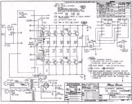
I can find any schematic about 700B complementary configuration but, if that can be of any help, here is the scheme of the 700 Series Two.
An externally hosted image should be here but it was not working when we last tested it.
Improved output and bias question
The image is for a better output stage than the one above. Faster and more stable with higher current capacity.
You will probably need to redo the bias a bit also but do not see that circuit. Can someone supply the inside of the amp schematic?
The image is for a better output stage than the one above. Faster and more stable with higher current capacity.
You will probably need to redo the bias a bit also but do not see that circuit. Can someone supply the inside of the amp schematic?
Attachments
Hi guys,
Thanks for the information posted. I see that the title of the schematic is '700 series two (comp)'. Does it mean that series two are comp.s or this is just a variant of the series two? What about the 700B? What would be the major difference between 700-B and 700-II? Which one is better in your opinion? Tks.
Thanks for the information posted. I see that the title of the schematic is '700 series two (comp)'. Does it mean that series two are comp.s or this is just a variant of the series two? What about the 700B? What would be the major difference between 700-B and 700-II? Which one is better in your opinion? Tks.
- Status
- This old topic is closed. If you want to reopen this topic, contact a moderator using the "Report Post" button.
- Home
- Amplifiers
- Solid State
- Phase Linear 700B power transistors upgrade