The Vgs in Chart1 only 2.2V maximum, It is too small cause the MOS current Id less 10mA.
What is the Vgs in your measure condition?
If the Vgs in your measure condition is from 0 to 10V,but the result of Vgs is less 3V, It may be the channel E can't keep the output regulator.
Check the result data,the column of 'Ve', It is the channel E output voltage.
In all measure procedure, The E channel output must regulator.
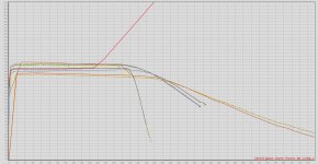
HEre is me measuring 5 different mosfets at 500 Rb and 4.55 Rc. Vce is fixed at 20V, Id max is 1A, and Vgs goes from 0-10V. As you can see there is one clean curve, but every trace after the initial one gets worse.
It has worked flawlessly up to this point. Just dont know what has happened. Replaced all mosfets. Have switched to 1013CP opamps.
It has worked flawlessly up to this point. Just dont know what has happened. Replaced all mosfets. Have switched to 1013CP opamps.
Attachments
Hi locky,
I have got the files! The tracer number is 244. Could you please send me the .INI?
Thanks a lot!
I have got the files! The tracer number is 244. Could you please send me the .INI?
Thanks a lot!
You can join the mail list
uk.dir.groups.yahoo.com/group/CurveTracer/
The software & document have upload on it.
But every curve tracer have different '.INI' file, If you lost the ini file,you need to re-calibration and generate the ini file.
Please refer to the "Curve Tracer hardware manual" section "Instrument calibration".
Or sent me your curve tracer number and email, I will sent to you.
The figure have selected "cablibration before measure"?
Re-run the program and don't select "cablibration before measure" use different RB/RC combination to measure the curve again.
1.RB=1360K RC=1K
2.RB=91K & RC=1K
3 RB=91K & RC=75
4.RB=6K & RC=75
5.RB=6K RC=4.55
6.RB=500 RC=4.55
Because If the calibration relay have wrong, But if you force to calibration, the memory parameter will change, and the test will failure.
The memory parameter will restore by exit and re-run program again.
You also sent the PCB to me to repair.
Hi Locky,
Thank you for your support. I've done the same tests again, without calibration. For first 8 tests, the curve tracer works fine, but 9th test the problem occurs again (see attached picture)
I took out J1 and J2, and measured resistance across contacts:
J1:
NC contacts: 41/44 mOhm
NO contacts: 94/101 mOhm
Coil: 1162 Ohm
J2:
NC contacts: 176/240 mOhm
NO contacts: 10/14 mOhm
Coil: 1039 Ohm
Now that they are out, i will buy new relays next weekend.
thanks,
Ozzy
Attachments
Hi Locky,
Now that they are out, i will buy new relays next weekend.
thanks,
Ozzy
Same for me, I had irregular measured results and with the help from Locy_z, one of the relays was out. Since the relays look old, I changed all of them.
Also, I was told by the elec. shop that are two types of relays, one with built in diode and one without. Anyway, I used the one w/o.
cheers.
All relay is 24V,Hi Locky,
Can you please confirm that all relays are 24 Vdc? Because J6 installed by you is actually rated 12 Vdc (QIANJI JRC-19F DC12V 0.2W).
thanks
Ozzy
Locky,
Sorry I thought I had posted this. Its a new .cuv file of testing under the same condition as previous graph.
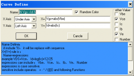
In curve define windows not select the 'Vce' & 'Ve' ?
Because all measure,the 'Ve' must stable. So selected the 'Ve' checkbox, It will put the Ve voltage in the tabular detail data.
But in your save data, there are not the 'Ve' data.
Attachments
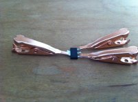
Thanks buzzforb. I assume "kinda high" refers to the price? Can you post or pm me a photo of your setup, just want to verify clip size and wire length (or did you solder pins to the clips and stuck those in the curve tracer?).I use small gator clips to measure sot223. They have adapters, but they are kinda high.
Radio shack sells them. As you can see, by flipping the SOT 223, you can have everything flat on a pcb. I have gate and Source clips soldered to pcb trace with drain attached to piece of wire for easy clipping. The board is designed to insert into the tracer inputs with right angle pins. I'll see if I can fish it out of dungeon.
Attachments
Thanks, hope you can find it!Radio shack sells them. As you can see, by flipping the SOT 223, you can have everything flat on a pcb. I have gate and Source clips soldered to pcb trace with drain attached to piece of wire for easy clipping. The board is designed to insert into the tracer inputs with right angle pins. I'll see if I can fish it out of dungeon.

Hi Locky,
Your tracer is no longer available on eBay? Are you out of stock? Will you have some new ones coming soon?
Because ebay only allow me sell 5 item once, When they sell out, I need to list them again, and the ebay link also change.
The lastest ebay link is: http://www.ebay.com/itm/locky-zs-Intelligent-curve-tracer-/111102327920?pt=LH_DefaultDomain_0&hash=item19de36fc70[/URL]
Last edited:
- Status
- This old topic is closed. If you want to reopen this topic, contact a moderator using the "Report Post" button.
- Home
- Amplifiers
- Solid State
- DIY Curve Tracer for PC