Revisited YAP v2.1
Schematic changes since the previous implementation (http://www.diyaudio.com/forums/showthread.php?s=&threadid=128809&highlight= )
- 4 pairs of 2SK1530/2SJ210 or IRFP244/IRFP9240 as output devices
- Improved overload protection (shuts down the entire output stage, thermal budget optimized)
- Temperature compensation supports both Toshiba and IRF MOSFET pairs.
- Active clipping protection, as per the VSOP amp
- Improved OPS input stage (following an idea by Andy).
- Output stage uses TMC frequency compensation.
- Alexander based input stage with improved current mirrors and Hawksford cascodes supports a variety of opamps, currently running on LME49710
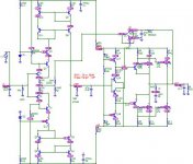
(These are the board level schematics, the output 1uH coil is dampened by 2.2ohm in parallel; Q114 is shorted for 2SK1530/2SJ201 only).
Construction changes since the previous implementation:
- Single 3.8" x 9.8" board construction.
- Supports both 2SK1530/2SJ210 or IRFP244/IRFP9240 power devices without any changes except the bias adjustment.
- 0.4W/C 5" x 11" Ro-Theta heatsink sections.
Measured (preliminary) performances:
- Output power: 2 x 200W/8ohm, 2 x 400W/4ohm, up to 2 x 600W/2ohm at +/-65V supplies from a 2KW toroid.
- Unity gain frequency: 4MHz
- Phase margin: 100 deg. Stable in all loads I was able to test, including 2uF series with 1ohm at 400W output power.
- Bandwidth: 10Hz-160KHz +/-0.5dB
- Non slewing; Rise fall times defined by the input filter <0.5uS
- Intrinsic slew rate >200V/uS
- Harmonic distortions: <0.0001% at all frequencies and power levels up to 200W/8ohm
- Harmonic distortions: <0.0003% at all frequencies and power levels up to 400W/4ohm
- IMD 19+20KHz: <0.0003% at all frequencies and power levels, up to 400W/4ohm.
- Ultra clean clipping, no sticking.
The PGP amp is there, in the dust.
Schematic changes since the previous implementation (http://www.diyaudio.com/forums/showthread.php?s=&threadid=128809&highlight= )
- 4 pairs of 2SK1530/2SJ210 or IRFP244/IRFP9240 as output devices
- Improved overload protection (shuts down the entire output stage, thermal budget optimized)
- Temperature compensation supports both Toshiba and IRF MOSFET pairs.
- Active clipping protection, as per the VSOP amp
- Improved OPS input stage (following an idea by Andy).
- Output stage uses TMC frequency compensation.
- Alexander based input stage with improved current mirrors and Hawksford cascodes supports a variety of opamps, currently running on LME49710
An externally hosted image should be here but it was not working when we last tested it.
An externally hosted image should be here but it was not working when we last tested it.
(These are the board level schematics, the output 1uH coil is dampened by 2.2ohm in parallel; Q114 is shorted for 2SK1530/2SJ201 only).
Construction changes since the previous implementation:
- Single 3.8" x 9.8" board construction.
- Supports both 2SK1530/2SJ210 or IRFP244/IRFP9240 power devices without any changes except the bias adjustment.
- 0.4W/C 5" x 11" Ro-Theta heatsink sections.
An externally hosted image should be here but it was not working when we last tested it.
Measured (preliminary) performances:
- Output power: 2 x 200W/8ohm, 2 x 400W/4ohm, up to 2 x 600W/2ohm at +/-65V supplies from a 2KW toroid.
- Unity gain frequency: 4MHz
- Phase margin: 100 deg. Stable in all loads I was able to test, including 2uF series with 1ohm at 400W output power.
- Bandwidth: 10Hz-160KHz +/-0.5dB
- Non slewing; Rise fall times defined by the input filter <0.5uS
- Intrinsic slew rate >200V/uS
- Harmonic distortions: <0.0001% at all frequencies and power levels up to 200W/8ohm
- Harmonic distortions: <0.0003% at all frequencies and power levels up to 400W/4ohm
- IMD 19+20KHz: <0.0003% at all frequencies and power levels, up to 400W/4ohm.
- Ultra clean clipping, no sticking.
The PGP amp is there, in the dust.
Very cool! A few questions...
The 1 Ohm resistors in the emitters of Q110 and Q116 - were they strictly necessary, or a "just in case" thing for the layout?
Regarding the 100 Ohm resistors in the collectors of these devices, what was the symptom when they weren't present? I assume parasitic oscillation? If so, roughly what frequency was the oscillation?
Is that TMC I see there in the output stage (C112, C113, R126, C123, C122, R158)? What effect do the 47 Ohm resistors have (R120, R164)?
Thanks.
andy_c said:Very cool! A few questions...
The 1 Ohm resistors in the emitters of Q110 and Q116 - were they strictly necessary, or a "just in case" thing for the layout?
Regarding the 100 Ohm resistors in the collectors of these devices, what was the symptom when they weren't present? I assume parasitic oscillation? If so, roughly what frequency was the oscillation?
Is that TMC I see there in the output stage (C112, C113, R126, C123, C122, R158)? What effect do the 47 Ohm resistors have (R120, R164)?
Thanks.
1ohm, provision for another configuration (that is, single ended input, then the resistors are required to bias the negative input pair).
Yes, parasitic oscillation. Frequency was about 60MHz. Even 47 ohm would do, I chosed 100ohm to stay on the safe side.
As mentioned above, it's TMC. 47ohm, increases the phase margin a bit (5-7 deg). To large and the phase peaks. 47 ohm seems to be an optimum here. Can be safely omitted but it won't harm to have a placeholder on the PCB.
BTW1, TMC is for the heck of it, TPC delivers exactly the same performance (I tested that in detail).
BTW2, I'm stumped by people stubbornly using IRFP240/IRFP9240 as "complementary" parts from IRF/Vishay. IRFP244/IRFP9240 is way better matching. In fact, according to my measurements, they deliver the same performance as the Toshiba pairs, at 40% the price. The only down size is with the headroom, the IRF pairs have large threshold voltages, they require Vgs about 4V for bias. The Vgs thermal coefficient is also different, but that can easily be compensated as in the schematic, using Q114.
Heh. Thanks for livening the place up. It was getting pretty bleak around here for a while there ") .
.
I'm familiar with the matching issue - you are right. I posted EKV models for the IRFP244 and Fairchild FQA9P25 (I needed the 250V capability in case the line voltage goes 10 percent high).
.I'm familiar with the matching issue - you are right. I posted EKV models for the IRFP244 and Fairchild FQA9P25 (I needed the 250V capability in case the line voltage goes 10 percent high).
Member
Joined 2009
Paid Member
Bigun said:Wow, this looks really interesting and it's completely unfamiliar to me along with some of the TLA's.
Do you plan to post the Spice file for others to play with ?
Unfortunately I'm using Cadence/PSpice and that's not very common across DIYers. It would be nice if a LTSpice user could re-capture the schematics and port the proper models.
why are the gatestoppers "unbalanced"
Different gate capacitances of N and P-channel part need different resistors for the same pole. They are only identical in case you use fets with identical capacitances (like the IRFP9240/IRP240), which however means that the N and P-fet has a different transconductance (all related to the different mobilities of the carriers, hole and electron).
Have fun, Hanes
So you drive 4 big output mosfets with only ~12mA of charging current (and much higher discharging to avoid cross-conduction)?
How is bias modulation at 20kHz?
P.S. Yes, I see C115, this should, to a degree mitigate bias modulation, but at the expense of slew rate.
What do I get wrong?
How is bias modulation at 20kHz?
P.S. Yes, I see C115, this should, to a degree mitigate bias modulation, but at the expense of slew rate.
What do I get wrong?
ostripper said:and what is the purpose of R133/149 (220k)?
OS
http://www.diyaudio.com/forums/showthread.php?postid=1600301#post1600301
Very nice,
I designed something in the same fashion not so long ago ( diamond fet input, current mirror VAS, diamond follower output, no feedback except DC) but more simple. I just had problems with the phase margin but with no AC feedback, it is not a problem I guess. The distortion is a little higher but only a few thouthands of % at full power so... I am sure yours is better but I like a little more simplicity!
Regards
Attachments
Member
Joined 2009
Paid Member
C115
Hi Adam,
These are good questions. I also have concerns, not only about this particular YAP-OPS, but also about more traditional OPS topologies.
In the past I've discussed this issue with Andy. Maybe he is willing to comment on this matter.
I'll send you a copy of my observations.
Cheers,
Edmond.
darkfenriz said:So you drive 4 big output mosfets with only ~12mA of charging current (and much higher discharging to avoid cross-conduction)?
How is bias modulation at 20kHz?
P.S. Yes, I see C115, this should, to a degree mitigate bias modulation, but at the expense of slew rate.
What do I get wrong?
Hi Adam,
These are good questions. I also have concerns, not only about this particular YAP-OPS, but also about more traditional OPS topologies.
In the past I've discussed this issue with Andy. Maybe he is willing to comment on this matter.
I'll send you a copy of my observations.
Cheers,
Edmond.
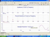
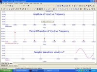
I don't know how it sounds (electronic is not my job, I am too busy these days) but I know how it looks on MicroCap. You can see the graphs for 1W and at clipping (clips at 40V peak, PSU at 45V) at 1 kHz. The distortion is just a tad more at 20kHz, but still less than 0.2% at clipping if I remember correctely. And take into account it is without feedback at all!
So 1 Watt
So 1 Watt
Attachments
syn08 on 08-28-2008 at 15:10:02[/i][b] [snip] 5. In both my simulations and experiments said:Revisited YAP v2.1
[snip]
- Output stage uses TMC frequency compensation.
[snip
 Did you see the light?
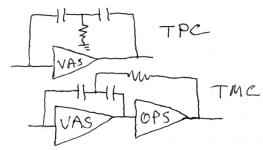
darian said:Sorry to sound dumb, but could you clarify what are TPC and TMC? I am not sure I know these acronyms!
Here's pics of TPC and TMC. TMC is a variant of Cherry's idea of putting the output stage inside the Miller loop. Cherry's idea is usually not stable. TMC is stable by virtue of taking the output stage out of the Miller loop at high frequencies.
Attachments
- Status
- This old topic is closed. If you want to reopen this topic, contact a moderator using the "Report Post" button.
- Home
- Amplifiers
- Solid State
- YAP power amp revisited, now at v2.1