Look I'm middle-aged these days and the memory is not what it was but I seem to recall there a correction published about the orientation of the 12volt zener........ I'll check my copies later to be sure.
Edit.
Sorry, false alarm. I've just dug my original copy out. The two circuits in this thread of the WW August '82 amp have already been corrected and the relevant zener and cap have been inverted.
Edit.
Sorry, false alarm. I've just dug my original copy out. The two circuits in this thread of the WW August '82 amp have already been corrected and the relevant zener and cap have been inverted.
Re: Fab's question about the 0.22 ohm resistor at the output.
The following is a quote from Hi-Fi News Record Review December 1972. It was the second part of a four part article on a 70 watt bipolar split rail amp.
"The final point of note on the simplified diagram is the 0.22 ohm resistor in the output to the loudspeaker. This serves to prevent DC negative feedback within the amplifier, which stabilises the DC working point voltage, from disappearing in the event of an inadvertant short circuit across the output."
But having said that, I seem to recall that he later also made the point that Salas makes. I can't find the quote exactly but I think it was to do with reducing the ammount of EMF that got back into the amp. I'll try and chase the reference up.
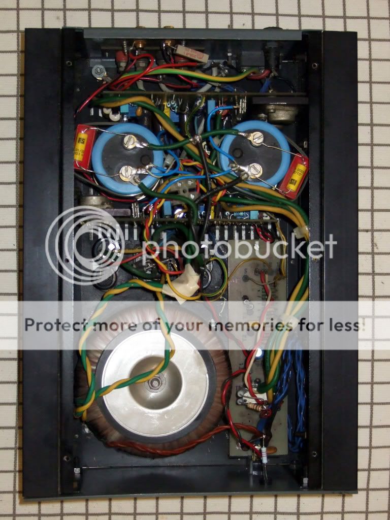
Looking like an amp again.🙂 Measures 0.00125% now. Remains to dig up my old 4mm terminated cables and give it a listen. I use Speakon terminated currently...
Forgot to ask...
I saw on the pcbs that the actual build does not have two 8V2 zeners as in the original schematic between sources and gates of the power Mosfets, but zener - diode protection combos as we see in many such amps. They are normally wired this way, in the various schematics.
I saw on the pcbs that the actual build does not have two 8V2 zeners as in the original schematic between sources and gates of the power Mosfets, but zener - diode protection combos as we see in many such amps. They are normally wired this way, in the various schematics.
Attachments


Jonathan Bright,
---I seem to recall that he later also made the point that Salas makes. I can't find the quote exactly but I think it was to do with reducing the ammount of EMF that got back into the amp.---
I recall it too.
A misconception to me.
Why EMF which shows up mainly as higher impedance should be reduced before the NFB treatment ? In amps having good stability, how NFB can be disturbed by EMF ?
The purpose of NFB is to make the amplifier voltage gain insensible to any disturbance happening at its output, isn't it ?
However, sure, a 0.22 Ohm does better than an output inductance to obtain square waves without overshoot on capacitive loads.
the poweramp, or any differential input amplifier, tries to adjust the output to bring the +in to match the -in signal after the NFB is connected.
If the output is uncontaminated then the the only signal coming back through the NFB to the input is a proportion of the output signal.
If one adds an extra signal to the output, interference, then a proportion of that is presented to the -in and the amplifier adjusts the output to bring -in back to match +in.
EMF at the output forces the NFB amplifier to make unwanted/unnecessary corrections that should not be required.
That to me seems to be an argument for increasing the attenuation of any external signal that is applied to the output.
Where has my understanding gone wrong?
The NFB has no way to distinguish internal disturbances (non-linearities, power supply injection) from external disturbances.
At each frequency, both are reduced by the amount of negative feedback at that frequency.
Just think of an amplifer under test, its input being shorted and its output connected to a resistor which, instead of being grounded, is connected to an other power amplifier which delivers test signals.
With a scope looking at the output of the first amplifier, you can observe the real impact of external disturbances on it.
Let's now consider a simple loudspeaker in a closed box. Its back-EMF is generated by the motional impedance. This motional impedance is in series with the voice coil DC resistance and some inductance.
For an 8 Ohm driver, this DC resistance is around 5 Ohm. Adding a 0.22 Ohm resistor in series at the amp output won't change much the open-loop attenuation provided by the dividing network formed by the driver series resistance with the effective open-loop output impedance of the amp (before the 0.22 Ohm resistor).
My PCB does not have the 0.22R, but I think that long enough cables will add some anyway. Any comment on the zener diode protection combo orientation that I have shown in the end of the previous page? Shall I change it?
Gave it a listen today. Cabling is different to speakers than my standard Mogami coax, its silver plated twisted VDH CS12. It sounds wider and more forceful in the midbass than the triode KT-88 amp, this must be directly relevant to the power and damping factor difference, grainless, open, attractive, but a bit more illuminated (not harsh) in the midhighs, than I consider totally natural. I will have to check the JLH in a second system with different speakers and everything else, so to be sure. Sounds very good class for initial evaluation. The ''illumination'' can very easily be the intrinsic quality of the coupling cap for instance. There is good information in its sound and its open and communicative.
I have to add a power Mosfet grid driver buffer in my KT-88 so to see if I can wake up the midbass presence. Because its more natural and informative in the highs. Difficult to get best of both worlds but I will give it a try.
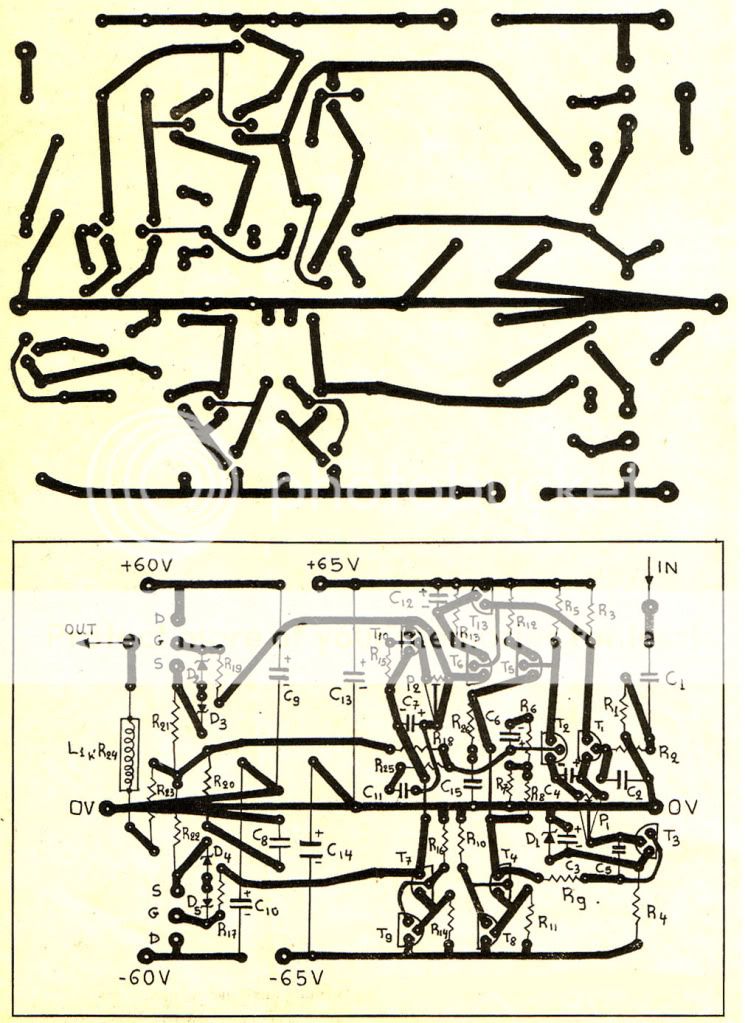
Here is a pcb that I found from a 1984 presentation of the amp in a Greek mag of that era. Maybe someone wants to try it if having some nos Hitachis. The correct print out dimensions must be scaled roughly at 125x85mm and this version is for connecting the Mosfets with short cables.
I have to add a power Mosfet grid driver buffer in my KT-88 so to see if I can wake up the midbass presence. Because its more natural and informative in the highs. Difficult to get best of both worlds but I will give it a try.
Here is a pcb that I found from a 1984 presentation of the amp in a Greek mag of that era. Maybe someone wants to try it if having some nos Hitachis. The correct print out dimensions must be scaled roughly at 125x85mm and this version is for connecting the Mosfets with short cables.
I removed the 10uF//10nF caps across the main filter reservoirs. HF ''illumination'' has gone by 90%. The amp seems neutral enough and lending itself to tonal manipulation easily.
Great to see another JLH thread.
I've got one of these. It's a fabulous amp.
Seeing this thread, I've dug out the original WW articles, June/July/August 1982.
The lack of L1 would account for your high THD.
JLH states that L1 is included to reduce the possibility of parasitic oscillation of the OP devices.
It's first function, however, is to reduce THD at high frequenceies, because it acts as a low-pass filter.
L1 should be 5uH, 20 turns of 24swg enamelled wire, wound around a 10R 1watt carbon rod resistor.
Yes indeed, the more it plays it more reveals itself as a very good amp.
It has L1 now and sounds smooth with 5m twisted pair cable on 3way speakers.
There is life in the main PSU caps still. Sounds powerful.
Does the original article give any check voltages?
Do you still listen to yours from time to time?
It has L1 now and sounds smooth with 5m twisted pair cable on 3way speakers.
There is life in the main PSU caps still. Sounds powerful.
Does the original article give any check voltages?
Do you still listen to yours from time to time?
Glad you got it fired up.
I must be honest, with my cloth ears, I can't tell my JLH96 apart from my JLHMOS82.
I can tell slight differences between my JLH69 and JLH96.
No, the original article doesn't list any voltages on the circuit.
I could do this for you, if you like, but probably not for a week or so.
I do dig it out from time to time, but have not done so for a while.
Probably does not matter.But in this amp, they are wired this way. Can they create a problem being wired like this? Shall I reposition them like in the above picture?
Hi Salas,
my experience with these fets is that they don't like wires, causes oscillations. I wonder how well the boards you have posted will work. It would probably not be difficult to change the outputs so they are mounted directly on the board.
Funny, last night I got out my old baby Perreaux 1050B (same fets). I dusted it out, and looked at the build quality which is very good for the mid eighties.
It sounds very good, maybe a little veiled. I think its time for some new caps.
I have seen them working with rather short wires on that magazine, they had photos and measurements back then. But I have used direct to PCB with L-Bracket to sinks on my own that some local shop had made in the 80's from that article anyway. Can 2SK1058 & 2SJ162 work OK and also go vertical not needing the bracket? Looks like they can, with some retouch on that hand drawn old PCB work.
2SK1058/2SJ162 should be very suitable.
Direct replacement almost of 2SK135/2SJ50
IRFxxx replacement is more questionable.
You would need some mod of the VBE multiplier.
Direct replacement almost of 2SK135/2SJ50
IRFxxx replacement is more questionable.
You would need some mod of the VBE multiplier.
I have seen them working with rather short wires on that magazine, they had photos and measurements back then. But I have used direct to PCB with L-Bracket to sinks on my own that some local shop had made in the late 80's from that article anyway. Can 2SK1058 & 2SJ162 work OK and also go vertical not needing the bracket? Looks like they can, with some retouch on that hand drawn old PCB work.
It can work, but your approach is certainly better. It would be an interesting amp to make, I have some of those old hitachis🙂
- Status
- Not open for further replies.
- Home
- Amplifiers
- Solid State
- JLH 100W L-MOS 2nd Life