Your reference to the "Thiele" paper and also "Cherry" tells me that we are talking about the same thing.
JLH generally used the full Thiele Network.
Either the R+C preceeding the R//L, or The R+C after the R//L
As Thiele & Cherry show they both work.
After reading Cherry, I thought and experimented for a long time and eventually adopted the Pi filter arrangement.
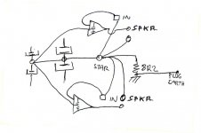
R+C at the amp output.
R//L in the line to the speaker terminals.
R+C across the speaker terminals.
Yes, I am interested. I learned a lot from the later Cherry paper in WW.
JLH generally used the full Thiele Network.
Either the R+C preceeding the R//L, or The R+C after the R//L
As Thiele & Cherry show they both work.
After reading Cherry, I thought and experimented for a long time and eventually adopted the Pi filter arrangement.
R+C at the amp output.
R//L in the line to the speaker terminals.
R+C across the speaker terminals.
Yes, I am interested. I learned a lot from the later Cherry paper in WW.
Okay Andrew, I suspect we are nearly discussing the same network......I don't want to debate this extensively without the paper in front of me (as the brain isn't using its search function as well as it used to!) but I think the Thiele network lacked the second resistor in series with the cap. I.e. L and R in parallel then a single cap' to ground which was then bridged by the addition of the speaker.......but without the conventional resistor it wasn't a classic Zobel......
It is coming back to me now. The theory assumed that the speaker was to be considered as a resistor. So then what the amp' "saw" was an L//R in series with a C//R (speaker) as the load.
If the inductor and capacitor values were chosen appropriately the load the amp' saw was largely resistive but with an ability to attenuate RF. Anyway I am not going to make a complete goose (technically a gander) of myself by rabbiting on in ignorance and as someone said of another; "When ever he speakers he subtracts from the sum total of human knowledge...!"
It will take a few weeks but the JAES article will surface before August.
Best wishes, Jonathan
With the Thiele Network, one sets the component values to what one thinks the amplifier needs to see.
At RF or Very High Audio Frequency, I think of the inductor as an effective open circuit and of the capacitor as an effective short circuit compared to the nominal load value.
The R//L becomes R'. The C+R becomes R".
The amplifier sees R' +R", one sets the two R values to whatever, the amp thinks it sees the same HF load.
Similarly when the C+R is before the R//L.
The amp sees R"//R' at HF.
I use the Pi version and the amp sees R"//[R'+R'"] at HF. The Pi is simply a trivial extension to the layouts that Cherry extracted from Thiele.
These are explained by Cherry's paper where he takes the two basic Thiele Networks and shows that there are a whole (infinite) range of values between the two limiting values used by Thiele.
JLH either recognised what was behind Thiele or discovered it by experimentation. Either way he adopted the Full Thiele Network rather than the Zobel Loading which exposes the amp to a potential short at HF if any parasitic capacitance exists beyond the amp PCB output terminal.
Last edited:
1nF & 4k7 gives 4.7us RF and Audio filter.
How low can this go and still stay free of oscillation? 330p, 220p, 150pF?
As far as I can recall JLH usually used the full Thiele Network on the output.
I had tried 330pF SM and it oscillated. That was when the output Zobel was still missing if I remember correctly.
Bandwith and phase response must be computed without input
and output filters to give an idea of the amp s caracteristics.
With the filters connected, the picture is made way more rosy,
although adding a zobel network will not change the THD ratios,
moreover at frequencies as low as 1KHZ.
Should have been the restoring of BC546s or something with renewing the soldering of components or wires then because the THD reduction at 1kHz was real by measurement.
Attachments
- Status
- This old topic is closed. If you want to reopen this topic, contact a moderator using the "Report Post" button.