Lumba Ogir said:Glen,
how long is your ignore list?
Not very. The list is rather pointless anyway as wingnuts on a mission keep replying to your posts anyway; usually with the added satisfaction of posting accusatory fantasies in the knowledge that they’re not going to be rebutted.
There is a much better option. I’m leaving this thread now. You can let this thread live by expounding the evils of two-pole compensation along with comrade Stuart if you wish.
G.Kleinschmidt said:The list is rather pointless anyway as wingnuts on a mission keep replying to your posts anyway; usually with the added satisfaction of posting accusatory fantasies in the knowledge that they’re not going to be rebutted.
Hey, you just gave me a great idea for a thread over in "Everything Else". It could be called, "Who's On Your Ignore List and Why?". Somehow I think it would be closed down pretty fast though. 😀
With regard to post 33, can somebody tell me what Q5 does. With the usual current mirror, Q5 is normally just a piece of wire.
My thought is that using Q5 equalises the Vce of the current mirror transistors. Am I correct?
My thought is that using Q5 equalises the Vce of the current mirror transistors. Am I correct?
Also are V6, V7, D3 and D4 required in order for the circuit to clamp properly.
If not, why are they there?
Thanks,
Ian
If not, why are they there?
Thanks,
Ian
With regard to post 33, can somebody tell me what Q5 does. With the usual current mirror, Q5 is normally just a piece of wire.
My thought is that using Q5 equalises the Vce of the current mirror transistors. Am I correct?
It is a current mirror with a beta enhancer which will mirror within a few nanoamps, my friend.
Page 7 , here .... http://kaflatooni.yasna.com/current_mirror_ref.pdf
OS
Hi
The schematic in post 33 is very simplified (ment for simulation only), so you should have a look at some of the other schematics to understand the circuit.
Q5 is a so called "helper" transistor. BTW: it should have been a resistor from the emitter of Q5 to Vcc, I guess Glen just forgot to put it there. 😛
D3 and D4 are clamping diodes, forget about V6 and V7, they are just meant for simulation (see the other schematics in this thread)
Hope it helped
Cheers 🙂
Thanks ostripper,
Simulations suggest that it clamps just as well without Q5 (replaced with a piece of wire), although D1 is now reverse biased typically 0.5V, depending upon the value of R5. Have you any reason to sugggest the circuit would not work as well without Q5?
Thanks stinius,
Simulations suggest that the current through Q5 looks ok without any additional resistor (presumably you meant in the collector, not the emitter?).
Almost as well. Q5 just improves the mirror a bit, hopefully improving DC offset a little, maybe reducing distortion a little...Have you any reason to sugggest the circuit would not work as well without Q5?
The resistor Stinius suggested is to get some extra current flowing through Q5 to improve it's performance e.g. current gain and speed.
btw: D1 and D2 are to limit the voltage swing at the base of Q6.
I now understand why Stinius said a resistor from emitter of Q5 to Vcc - give it more current.
Thanks Godfrey.
Thanks Godfrey.
Have you any reason to sugggest the circuit would not work as well without Q5?
I have used something like Q5 in a CM with both a LTP and a balanced VAS. WAY TOO MUCH GAIN. 😱 Made my amp unstable even with the resistor mentioned. Open loop gain was over 90DB in both instances.
Standard CM is plenty adequate with sufficient Hfe devices.
OS
Agreed, a standard CM is plenty adequate.
But how on earth you get "WAY TOO MUCH GAIN" when using a more accurate CM, i.e. when the current gain rises from say 0.99 to 0.9999?
But how on earth you get "WAY TOO MUCH GAIN" when using a more accurate CM, i.e. when the current gain rises from say 0.99 to 0.9999?
biased Q5 gives the potential for some modest distortion cancellation by matching Q5, Q6 devices, operating points - any time you go with the current mirror you've already bought into compensating a 2nd order system so I'm not sure there is a problematic stability cost to Q5 inclusion
but there is some 20 dB of audio frequency V gain still "left on the table" by the circuit shown - with or without Q5
but there is some 20 dB of audio frequency V gain still "left on the table" by the circuit shown - with or without Q5
Agreed, a standard CM is plenty adequate.
But how on earth you get "WAY TOO MUCH GAIN" when using a more accurate CM, i.e. when the current gain rises from say 0.99 to 0.9999?
I don't know , but when I used the beta enhancer on the CM of my balanced VAS (symasym type VA) It nearly broke out in oscillation.
Upon investigation in the simulator the VAS as a whole achieved 6db more OLG.
and it's unity gain point advanced by a couple hundred Khz. Upon removing the 3' rd tranny and resistor , all was stable. ???
OS
Interesting. Would you give me link to the "symasym type VA", please?
Cheers,
E.
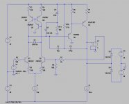
you know... the symasym VAS (VA) , with its current mirror at the bottom. Standard stuff. 🙄
Ok.. picture..(below)
OS
Attachments
Please, come on!you know... the symasym VAS (VA) , with its current mirror at the bottom. Standard stuff. 🙄
Ok.. picture..(below)
OS
 You were just describing something weird, that makes no sense at all. As I'm curious why it went wrong, in particular when it is not obvious (we all can learn from that), I need to know all the details, that is, a complete schematic.
BTW, "standard stuff" don't oscillate with a slightly improved current mirror. 🙄
Weird indeed, but...
I'd expect the performance of the mirror in post 117 to be dismal without a cascode on Q11.
DC voltage on the collectors of Q10 and Q11 is badly mismatched and Q11 has full output voltage swing on it's collector. (Consider Early effect, Miller effect etc)
The 6dB increase in overall gain at HF is probably just the result of bringing the mirror from near death back to normal operation.
e.g. Having the helper transistor drive Q11's Miller capacitance is a big step forward.
speculation?
I don't think that a (gross) Vce mismatch could explain a difference of 6dB in gain. But that 6dB itself makes me also suspicious.
>The 6dB increase in overall gain at HF is probably just the result of bringing the mirror from near death back to normal operation.
Exactly! This is precisely what you would expect if one of the branches of the VAS (Q7 respectively Q11) wakes up from an inactive state (i.e. behaves like CCS or so) to an active state.
- Status
- Not open for further replies.
- Home
- Amplifiers
- Solid State
- A superior VAS clamp and VAS current limit for the Blameless.