nigelwright7557 said:I now use +/-60V and that seems to be a lot better.
Sadly the price of electrolytics rockets above 63V.
Amplifier power rockets above 63V, too. And amp rails are never as stiff as you expect them to be based on trafo regulation specs.
wg_ski said:
Amplifier power rockets above 63V, too. And amp rails are never as stiff as you expect them to be based on trafo regulation specs.
Thats becasue the output power is V squared/ speaker impedance.
Why are you needing all that power Satji?
Do you have speaker enougth to all that power?
Will be some special application, alike football field or enormous open air alive performance or something in a such direction?
Man!.... this heatsink cannot hold all that power.
I feel curious....just that.... i have some speaker here, used into automobile, so bad they are(low efficiency) that needs 400 watts RMS to move..is this your case?
Carlos
Attachments
I understand that some applications needs power.
I am very curious about yours....please, let me know.
regards,
Carlos
http://www.youtube.com/watch?v=2SBEJffbwHk
I am very curious about yours....please, let me know.
regards,
Carlos
http://www.youtube.com/watch?v=2SBEJffbwHk
I want to use it for 2 different application:
- home system to drive my 8ohms Focal loudspeaker, mainly in class A, up to 100W.
- to drive the front, and subwoofer in a party (my subwoofer contains 2x18" Beyma loudspeakers, and can handle 1800W rms)
I know that this heatsink is not enough. This is for test only. I'm not sure the final solution. I have two possibilities:
1, 40cm long heatsink for each module
2, keep this heatsink, and use forced cooling with variable speed fan
Sajti
I had no time in the last few weeks, but now I start to do some measurements, and try some other solution.
So, the prototype contains now: 4pairs of MJL21193/94, and NJW0281/0302 as drivers and no predriver. I measured the input impedance, which is 12kohms, with 2ohm load (it means 4ohm nominal load for the bridged amplifier). It's not so hard load, and I can drive it with White follower using ECC99 (150V/18mA anode current). I still working to put it together...
Sajti
tell me if this is balderdash.
Maximum output 30Vpk.
Maximum current into 2r0 15Apk.
Maximum current into 2ohm ~45Apk.
Maximum current through each output device ~5.6Apk (during normal use - no abuse).
typical gain @ 5.6Apk ~ 45 to 60.
typical maximum base current ~45Apk/45 ~1Apk.
typical NJW gain @ 0.1Apk to 5Apk, ~constant @ 100.
typical driver base current ~10mA+driver bias ~?mA. Try 20mA
typical impedance 30V/0.02A ~1k5 for normal drive conditions.
The idea comes to my mind, when I measured the ECC99 white follower capacity, and I found that it can do almost 35V peak when clipping into 1kohm load. So 30V is possible with less than 0.5% distortion.
Maybe I will try to use NJW3xxxs as output devices too, because the SOA is not very critical with bridged amplifier, and it has little higher gain at that current.
Sajti
Maybe I will try to use NJW3xxxs as output devices too, because the SOA is not very critical with bridged amplifier, and it has little higher gain at that current.
Sajti
16pairs for 220W into 8ohms.8pairs of NJW0281/0302 as output,......
......... The 2 amplifiers is bridged for 220W/8ohms
A three pair Leach does 170W into 8ohms.
For an easy design, consider a pair of LM3886 with 0R68 in the power supply pins.
Drive 4 outputs per power supply pin (a total of 16 per mono channel).
General idea:
Use something like 0R22 in the emitter of each output device, and adjust the value of the 0R68 in the drive pins if you want some sort of current limiting. Mount the LM3886 to track the temperature of the outputs, it has temperature shut-down built in.
Drive 4 outputs per power supply pin (a total of 16 per mono channel).
General idea:
An externally hosted image should be here but it was not working when we last tested it.
Use something like 0R22 in the emitter of each output device, and adjust the value of the 0R68 in the drive pins if you want some sort of current limiting. Mount the LM3886 to track the temperature of the outputs, it has temperature shut-down built in.
Last edited:
I want to build 900W/2ohms bridged amplifier, which will use 8 pairs of MJL21193/94, in each amplifier module, with +/-37V PSU.
My only problem, how to drive this amount of output devices? There are 3 options:
1, Drive with same type of transistor. One more pair MJLs with 150-200mA bias, or
2, Parallel connected MJE15032/33, with 70-80mA bias in each pair. Two or three parallel, with base stopper, and small series emitter resistors, or
3, Separate the output devices to 4-4pairs, and drive them with separated driver (MJEs) I don't know which would be better. sajti
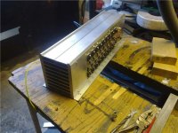
Also a good solution is the use of a multi emitter power BjT for driver. This was done by Electro Voice P2000 (P 2000) and by the Dynachord L1600 (L-1600)
(see attachement)
Attachments
Also a good solution is the use of a multi emitter power BjT for driver. This was done by Electro Voice P2000 (P 2000) and by the Dynachord L1600 (L-1600)
(see attachement)
I use something like that, but with tube VAS, and balanced output (bridged configuration). The only question if I need as much output devices as I tested.
Regards:Sajti
NJW0281/0302 output devices: I read many times in this forum, that this devices are factory selected for 10% gain difference. So I have 140 pcs. of NPN, and same number of PNP devices. No fakes (all ordered from Mouser, which is good source, I believe).
So I want to select pairs for my amplifiers. I measured all devices with Vce=5V, and Ic=100mA. This current is close to the bias, I want to use.
Just for fun, I tried with Ic=10mA, and Ic=1A as well, but there was no significant difference, so the the gain is quite flat.
The NPNs have really bad results on this test. The Hfe disperse from 84 to 122. The low gain is more typical, there are only few high gain (over 110) device found. But more than 50% of the transistors are below 90
The PNPs are very good: the minimum gain is 97, and the maximum is 118. But only 10 found over 110, and only one less than 98. So I can tell that the 10% is true for PNP devices!
The final result is 56 pairs from Hfe= 98 to Hfe=110. The pairs are within 1%.
Sajti
- Status
- This old topic is closed. If you want to reopen this topic, contact a moderator using the "Report Post" button.
- Home
- Amplifiers
- Solid State
- How to drive 8 pairs of MJL21193/94?