Member
Joined 2009
Paid Member
Back to the Lender VAS,
with some help from OS it is morphing into something and the student (I) am liking it more as I learn about common base amplifiers.
Common base has a low impedance input which is fine because the LTP in TGM2 has plenty of drive for that. It also has excellent voltage gain - potential for lots of swing. This is an important attribute for the VAS.
I also don't see Cdom being such a problem in common base configuration, so good for HF and good isolation between input and output so not too much instability to worry about.
Trying this out on my pcb is a bit tricky. I'll have to make some changes, pull out a resistor (R4) and short it, add fly wire + resistor to connect up the other diff device collector to the VAS, maybe flip around the VAS device on the pcb since it's e-c-b can make it b-c-e. hmmmmm, will have to check if this is possible without making a mess.
Member
Joined 2009
Paid Member
Lumba Ogir said:Gareth,
now you are on the right track.
Good, the student needs positive feedback (and guidance from Lumba, OS, MJ, Carlos etc.) to stay on track
and I will make the Master happy, to rid my amplifier of the Cdom
")
Hi Gareth,
You made some interesting observations here. Colin and I have done some work on this topology and can contribute a bit more here. (Colin is in Vancouver, BTW). You said this:
As we know, common base holds base at a reference voltage, signal input to emitter, and signal output at collector. Input impedance is very low, as the injection point is effectively a virtual earth, and very similar to the folded cascode input situation.
However, output impedance is very high, as you'd expect from a reverse biased junction. It is high for all collector outputs except the CFP, so there is no advantage there.
You are right on the money with voltage gain, see here. The increased voltage gain will improve feedback factor for the complete amp, but because input and output phase are identical, there is less overall phase shift than a common emitter amp, and this increases the pole frequency (essentially it's a faster configuration, commonly used to drive RF amplifiers), making Nyquist criteria for stability a little easier to achieve - that is, smaller Cdom.
However, Cdom is difficult to implement because there is no phase reversal, so a simple cap from collector to base is not possible. Shunt compensation to ground is possible, certainly this works, as Colin and I have found, but it's not as effective and you need more of it. You can also use phase lead to the feedback node, which is problematic, but another LC trick is to string a cap from output to the antiphase side of the LTP, which shoud be resistively loaded to give a reverse phase signal.
If you use the Lender configuration, you can still use standard lag compensation, but enjoy the benefits of common base AND common emitter. Incidentally, in simulations I found that there is no gain advantage with the Lender over the standard single ended common emitter, since the emitter degeneration needed for the Lender scotches any increased gain you might otherwise derive from differential drive. In simulations the OLG appears to be identical either in diff, Lender drive or SE common emitter drive. However, the Lender does combine some of the characteristics of a good current mirror, as it very effectively forces current balance in the LTP.
Hope this is helpful,
Cheers,
Hugh
You made some interesting observations here. Colin and I have done some work on this topology and can contribute a bit more here. (Colin is in Vancouver, BTW). You said this:
Common base has a low impedance input which is fine because the LTP in TGM2 has plenty of drive for that. It also has excellent voltage gain - potential for lots of swing. This is an important attribute for the VAS.
As we know, common base holds base at a reference voltage, signal input to emitter, and signal output at collector. Input impedance is very low, as the injection point is effectively a virtual earth, and very similar to the folded cascode input situation.
However, output impedance is very high, as you'd expect from a reverse biased junction. It is high for all collector outputs except the CFP, so there is no advantage there.
You are right on the money with voltage gain, see here. The increased voltage gain will improve feedback factor for the complete amp, but because input and output phase are identical, there is less overall phase shift than a common emitter amp, and this increases the pole frequency (essentially it's a faster configuration, commonly used to drive RF amplifiers), making Nyquist criteria for stability a little easier to achieve - that is, smaller Cdom.
However, Cdom is difficult to implement because there is no phase reversal, so a simple cap from collector to base is not possible. Shunt compensation to ground is possible, certainly this works, as Colin and I have found, but it's not as effective and you need more of it. You can also use phase lead to the feedback node, which is problematic, but another LC trick is to string a cap from output to the antiphase side of the LTP, which shoud be resistively loaded to give a reverse phase signal.
If you use the Lender configuration, you can still use standard lag compensation, but enjoy the benefits of common base AND common emitter. Incidentally, in simulations I found that there is no gain advantage with the Lender over the standard single ended common emitter, since the emitter degeneration needed for the Lender scotches any increased gain you might otherwise derive from differential drive. In simulations the OLG appears to be identical either in diff, Lender drive or SE common emitter drive. However, the Lender does combine some of the characteristics of a good current mirror, as it very effectively forces current balance in the LTP.
Hope this is helpful,
Cheers,
Hugh
Member
Joined 2009
Paid Member
Hugh,
Thanks for helping, it is always appreciated, and as always, you are way ahead; I had not stopped for a minute to consider how to achieve effective compensation once Cdom was slain.
TGM already incorporates some HF feedback from the VAS to the feedback node. I see what you mean by 'problematic' - both ends of that cap will now be at the same phase. I like your suggestion of compensation by finding the 180 degrees phase difference from the other side of the LTP.
With compensation I worry less about stability but more of how to ensure good sonics, no doubt because I haven't fried my amp with oscillations (yet). From your experience with these things, what is going to preserve / enhance the sonics that I am already enjoying ?
I will try something on a sim which I can run at work next week - die hard Mac fan at home, no Spice (plus I can see what OS does with the RCA 'back to the future amp' mods). I don't think I can bear to mess up my current pcb now that I'm listening to it.
You have me worried about the original Lender that I started with, I don't like the idea that it has 'current mirror' tendencies; some prejudices are useful in constraining the scope of this project
Gareth,
I cannot answer your question, but in typically confucian mode I can suggest questions...
Music is a subjective thang, and different topologies seem to suit different folks. Roender likes differential folded cascode, Scott Wurcer likes fully complementary input stages with diff VAS, I like single ended input stages (yes, even singleton's, which work very well!), but from a measured standpoint some are better than others.
However, from a sonics POV, the one which matters to me as I've never sold an amp to a customer with an AP distortion meter in his listening room, I favour single ended designs, and I like the simple common emitter amp, I like the Lender, and I like a buffered VAS. I've had some success commercially with very simple amplifiers using the old RCA Lin topology and honing the dimensioning and component choices.
So, while the sexy part of audio design involves imaginative topology choices, careful simulations and other highly mathematical investigations, I tend to think that the sonics lie, as they do in many technologies, with careful, dimensional fine tuning and synergistic component choices. I can ruin the sound of an amp with a bad choice of compensation cap, for example, as you've just found. Move it up or down by more than about 15% and you lose all the magic, as you put it. I'd even suggest that 70% of the design game lies with this one cap.
The unsexy aspects are component choice and dimensioning. Since we are working towards marginal improvements, it's precisely these areas which take lots of time, and huge iteration, which is mind numbing. Perhaps because of long years of military service during peace, I find this not too difficult.... however, my ears are now so bad I depend more and more on others with good ears, like Colin, Huy, and several others who hear absolutely everything.
The technical approach, laden with math and sharp observations about stability criteria, have their place, but rarely do academic designs sound marvellous. I'm pretty sure I know why, but it's taken years to confirm it, and the reasons are not popular in these parts.
Sorry, no easy answers...
Cheers,
Hugh
AKSA said:The technical approach, laden with math...
Math is only a burden for those who do not understand it. For those who do, it is an enabler.
...and sharp observations about stability criteria, have their place, but rarely do academic designs sound marvellous. I'm pretty sure I know why, but it's taken years to confirm it, and the reasons are not popular in these parts.
I don't take issue with any claim along the lines that an incompetent hack, randomly changing components, can make a really good-sounding amplifier. I only take issue with your claim that only an incompetent hack who randomly changes components can make a great-sounding amplifier. This is not something that only occasionally comes up either. You repeat it so often it deserves "big lie theory" status.
 OT and personal posts removed. Keep to technical discussion.
I only take issue with your claim that only an incompetent hack who randomly changes components can make a great-sounding amplifier.
This is darkly false. I do not make that assumption. I say that a competent technician with reasonable equipment, a thorough knowledge of Ohms and Kirchoff's laws and a good ear can design an exceptional amplifier, quite the opposite of your contention. A strong knowledge of the history and theory of amp design is helpful too. Your laughable assumption shows sloppy thinking of a subjective, non-scientific kind - precisely what one would expect of someone with a very large axe to grind and arguably a vested self-interest in promoting the glory of mathematical ability.
Besides, where are the double blind tests which clearly show 100% correlation between low measured, single tone THD and subjective listening pleasure?
Have a nice day!
Member
Joined 2009
Paid Member
Back on topic
Guys, you have my grey matter in over-drive trying to learn about common base.
I am thinking more about the common base. And I see that the simple implementation is now quite a problem for the LTP balance. My first set of simulations showed an increase in distortion and I think this is the cause.
And as I established a constraint of no current mirrors, so it leaves me with few options. I tried to find some ideas from the tube guys, who seem to like common-grid for phono stages [http://www.tubecad.com/2007/08/blog0116.htm]
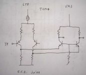
One option is to go more symmetrical. I make two common base VAS devices, driven by each side of the LTP. This way the LTP is loaded the same on both sides. Sketch attached (you can see Lumba's schematic showing through from the other side of my sketch!).
Not sure yet if this common base has enough drive capability for the output. Self shows several VAS improvement schemes but points out that the non-linear input impedance of the output stage requires buffering.
Guys, you have my grey matter in over-drive trying to learn about common base.
I am thinking more about the common base. And I see that the simple implementation is now quite a problem for the LTP balance. My first set of simulations showed an increase in distortion and I think this is the cause.
And as I established a constraint of no current mirrors, so it leaves me with few options. I tried to find some ideas from the tube guys, who seem to like common-grid for phono stages [http://www.tubecad.com/2007/08/blog0116.htm]
One option is to go more symmetrical. I make two common base VAS devices, driven by each side of the LTP. This way the LTP is loaded the same on both sides. Sketch attached (you can see Lumba's schematic showing through from the other side of my sketch!).
Not sure yet if this common base has enough drive capability for the output. Self shows several VAS improvement schemes but points out that the non-linear input impedance of the output stage requires buffering.
Attachments
Hi . Gareth. Your latest image looks like the Roenders's amp , at least in principle. He cascoded both LTP and the balanced VAS to come up with his final amp.
Here you hit the "nail right on the head" concerning my design choices. I was "torn" between roender's amp and the symasym. With more than a couple OP pairs , I needed more drive. While I do admit that the common base sounded better (by a VERY small margin), I would of needed a triple EF and 4 extra components for the LTP/VAS (cascodes) to both be able to drive a large OP and run the common base precisely.
While I thought that using no typical Cdom was real cool (wow , the speed- perfect 50Khz squares with almost 100 v/us slew) , it was very hard to differentiate the sound from the enhanced symasym. (both sounded great)
Another point to make , the ideal balanced VAS does use a CM, not on the input pair , but right on the VAS. Some , like Roenders and MJL's , even use a Wilson mirror CM.
OS
Not sure yet if this common base has enough drive capability for the output.
Here you hit the "nail right on the head" concerning my design choices. I was "torn" between roender's amp and the symasym. With more than a couple OP pairs , I needed more drive. While I do admit that the common base sounded better (by a VERY small margin), I would of needed a triple EF and 4 extra components for the LTP/VAS (cascodes) to both be able to drive a large OP and run the common base precisely.
While I thought that using no typical Cdom was real cool (wow , the speed- perfect 50Khz squares with almost 100 v/us slew) , it was very hard to differentiate the sound from the enhanced symasym. (both sounded great)
Another point to make , the ideal balanced VAS does use a CM, not on the input pair , but right on the VAS.
Some , like Roenders and MJL's , even use a Wilson mirror CM.OS
Member
Joined 2009
Paid Member
Thanks OS. I think I am finally starting to understand some of these things, way more complicated than I thought only two weeks ago - I guess the more you know, the more you realize you don't know.
I am lucky enough to have a Patchwork amp on my desk, I agree, MJ's design is very nice.
I am lucky enough to have a Patchwork amp on my desk, I agree, MJ's design is very nice.
Member
Joined 2009
Paid Member
OK, it's sunny and I have to stop 'work' and go make a BBQ etc.
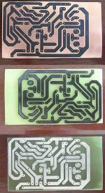
But I have started on the 2nd channel. No changes to the pcb. I will use these first two channels for the rear speakers (I will consider improvements for the front three).
And to prove that pcb making frustrations are behind me, (top image) toner transfer worked nicely first time, (middle image) etched and (bottom image) drilled (need to re-drill for large components):
Attachments
Member
Joined 2009
Paid Member
And finally
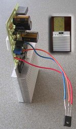
I now have a 2nd channel of TGM1. I checked dc offset (both channels too high of course), adjusted the output pair biass current, then connected it up. First listening test was with the DIY Fostex, a much cheaper 'fuse' than my PMC speakers
I find these Fostex 127 drivers really detailed and the amps have nothing bad to say about the music at all (except the hum that I haven't fixed yet which is louder with these more sensitive speakers). It sounded very good to my ears.
Still lots to do, but being able to sit and listen in stereo is a key milestone. And a good time to thank everyone again for their help and encouragement, you made a good amplifier!
I'm not sure if this is the last of the TGM1's - it wasn't intended to be one of those amps that others would build and the two channels I have will go into service for the rear HT channels. Next up I have a chance to try and build the TGM2 for the front channels and learn some more.
Still sounds good on the PMCs now, but my initial feeling is that the Fostex units make a surprisingly good match with this amplifier. We know this type of topology is a little warmer than some of the more accurate amps and these speakers sound to my ears to be very much at home with this type of amplifier. More listening time is needed.
Attachments
AKSA said:
Besides, where are the double blind tests which clearly show 100% correlation between low measured, single tone THD and subjective listening pleasure?
Have a nice day!
I'm curious could you elaborate? Is that low as in some is bad and the absense is good or is that low as in none is bad and some low amount is pleasurable. I am really curious since you did not quote the source.
On vinyl it's moot there is so much low order tracking distortion for any real cartridge the electronics are irrelevant.
Member
Joined 2009
Paid Member
Hugh,
You have found me out
It really hasn't been an objective/subjective issue with me, I came to this without the weight of all the historical discussions that have been going on in the audio world. All I needed to do was build it and listen to it in comparison with my Bryston (relatively free of harmonic colour).
Another hobby of mine is photography. Before it went ClassD (errr, I mean digital) people would evaluate different film stocks. Manufacturers publish detailed specifications for their film and add a subjective characterization by calling it 'vivid' or 'warm' etc. Photographers choose a film based on their subjective evaluation of the results. The strange thing is, they don't seem to have a conflict between objective and subjective.
I have decided that my next project will be stereo and I will design the amplifier to allow me to change its characteristics to suit the speaker and the type of music I am playing.
I'm sure that some people do this in the digital domain (like photographers) and then output via a colour-less amplifier - both solutions are valid.
Hi Scott,
I asked for the double blinds that show a correlation. I have never seen any, have you by any chance?
All amps distort, and vinyl distorts horrifically as you mention, mostly H2/H3/H4.
Zero distortion would be good, agree. But it's almost unrealisable. And global negative feedback, while reducing amplitudes, seems to synthesize artefacts well into very high harmonics. Doubtless these beat, and produce audible outcomes.
I'm very concerned about very low levels, below -80dB, of H5, H7, H9. These to me are a primary concern, because they appear to subliminally cause problems.
Some low amount of H2/H3 appears to be pleasurable to many, viz the vinyl and tube set.
THD is an rms summation; gives no real indication of the profile of the distortion. This harks back to Hiraga's notions of the monotonically decreasing distortion profile, which is certainly what I aim for.
My source is normally the ubiquitous CD; I use a tube preamp to add a bit of low order, but the equation changes with a vinyl rig. You essentially need no tube preamp then.
Further, it's a fact that people's tastes vary. Some like utterly distortion free sound, others like a bit of 'warmth'. Consequently good design is something of a moving target.
Liked that recent circuit of yours, very clever,
Cheers,
Hugh
I'm curious could you elaborate? Is that low as in some is bad and the absense is good or is that low as in none is bad and some low amount is pleasurable. I am really curious since you did not quote the source.
I asked for the double blinds that show a correlation. I have never seen any, have you by any chance?
All amps distort, and vinyl distorts horrifically as you mention, mostly H2/H3/H4.
Zero distortion would be good, agree. But it's almost unrealisable. And global negative feedback, while reducing amplitudes, seems to synthesize artefacts well into very high harmonics. Doubtless these beat, and produce audible outcomes.
I'm very concerned about very low levels, below -80dB, of H5, H7, H9. These to me are a primary concern, because they appear to subliminally cause problems.
Some low amount of H2/H3 appears to be pleasurable to many, viz the vinyl and tube set.
THD is an rms summation; gives no real indication of the profile of the distortion. This harks back to Hiraga's notions of the monotonically decreasing distortion profile, which is certainly what I aim for.
My source is normally the ubiquitous CD; I use a tube preamp to add a bit of low order, but the equation changes with a vinyl rig. You essentially need no tube preamp then.
Further, it's a fact that people's tastes vary. Some like utterly distortion free sound, others like a bit of 'warmth'. Consequently good design is something of a moving target.
Liked that recent circuit of yours, very clever,
Cheers,
Hugh
AKSA said:
I'm very concerned about very low levels, below -80dB, of H5, H7, H9. These to me are a primary concern, because they appear to subliminally cause problems.
Cheers,
Hugh
Hello Hugh
Maby those very low levels of H5, H7, H9 do mix-up the way the brain are doing the psychoacoustic reconstruction of the music we are listening. So we could lost some soundstage and feel some kind of discomfort wen there is those H5, H7, H9 distortions harmonics in a amp.
So assuming that the brain use high frequencies as psycoacoustic marker (or references) to find out what was the sound levels, the positions of instrument in space and the sound personality of them, if the distortion do have some high frequencies harmonics the psycoacoustic marker are poluted and the brain cannot reconise the fine details and the psycoacoustic references, so it try to reconstruct the music with some loss, difficulties and discomfort.
But if you mask those high frequencies harmonics distortions with some low level and low frequencies harmonics, maby the brain will reconstruct the music with less difficulties, because that the poluted high frequencies psycoacoustic marker are masked, and the brain can use it memories of sound to compensated and give a better or a less stressing result.
Bye
Gaetan
- Status
- This old topic is closed. If you want to reopen this topic, contact a moderator using the "Report Post" button.
- Home
- Amplifiers
- Solid State
- TGM Amplifier ?