Hi all,
since the original Krill thread has become way too big I think that is better to start a separated thread dedicated to building questions and experiences.
This way the information for building a Krill amp will be easily available.
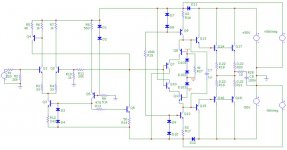
Attached the schematic for the 100W amp.
Some notes:
-R5 is actually a 100 Ohm fixed resistor paralleled with a 100 Ohm trimpot
-I omitted the 100Ohm//1K trimmers between the emitters of Q7/Q10 and the collectors of Q8/Q11 since these are not present on the boards.
-R27 is the bias trimmer
Ciao
Andrea
since the original Krill thread has become way too big I think that is better to start a separated thread dedicated to building questions and experiences.
This way the information for building a Krill amp will be easily available.
Attached the schematic for the 100W amp.
Some notes:
-R5 is actually a 100 Ohm fixed resistor paralleled with a 100 Ohm trimpot
-I omitted the 100Ohm//1K trimmers between the emitters of Q7/Q10 and the collectors of Q8/Q11 since these are not present on the boards.
-R27 is the bias trimmer
Ciao
Andrea
Attachments

Hi Thomas,
I've completed one channel but I'm experiencing biasing troubles.
It looks like Q7 and Q10 get too hot and "cut" the bias. I'm not able to set the bias higher than 20mA/device at the moment without cooling them.
I informed Steve and will post progress here.
Ciao
Andrea
I've completed one channel but I'm experiencing biasing troubles.
It looks like Q7 and Q10 get too hot and "cut" the bias. I'm not able to set the bias higher than 20mA/device at the moment without cooling them.
I informed Steve and will post progress here.
Ciao
Andrea
Andrea,
they each dissipate around 600mW, so maybe good heatsinking is required..... I guess the low Vbe at high temps cuts off the bias string completely. It is surely just a temperature effect.
Hugh
they each dissipate around 600mW, so maybe good heatsinking is required..... I guess the low Vbe at high temps cuts off the bias string completely. It is surely just a temperature effect.
Hugh
Hugh,
I agree that the cause is most likely a temperature effect, but I'd like to hear also Steve's opinion about it, since he never mentioned the requirement for heatsinking (he stated that the BJTs run hot on purpose) and also because those boards were used for a commercial 100W monoblock amp.
Ciao
Andrea
Originally posted by Steve Dunlap:
The rest of the TO220 devices will dissipate about 0.35W each and should not need heat sinking. I run them warm on purpose.
I asked: Which purpose?
and Steve answered:
I have been waiting for someone to ask that question. At 10mA of current the transistors run at an elevated temperature for two reasons. One reason is the increased gain and linearity. The other is that this pretty much swamps any change in die temperature caused by changing output current in these devices.
Hi Andrea,
Q9 and Q12 should be running at about the same temp as Q7 and Q10. Is this the case? You should just be able to keep a finger on the transistors. If they are too hot for that, check to see that you have no more than 10mA through R16 and R17. I have not encountered this problem before. If the transistors are getting too hot and cutting bias, and all else checks out OK, you can either use a small heat sink on the transistors or increase the value of R16 and R17 to reduce the current.
Q4 and Q6 should also run at the same temp, but they will not effect the bias.
boraomega,
Andrea is building the 100W version. The transistors in it will dissipate about 0.56W. Still well below the 2W rating.
Andrea is building the 100W version. The transistors in it will dissipate about 0.56W. Still well below the 2W rating.
I'm putting together a BOM for parts for the 100W version as posted on thread 1013 on the original Krill thread. It's attached here for reference. As a rough starting point, the parts to build the amp according to that schematic are about $90 per channel, exclusive of transformer, chassis, hardware, heatsinks, etc.
I'll post the BOM once I check it against the boards, especially as Andrea mentions that there are no provisions on the boards for some of the potentiometers.
Also, the schematic shows R21 and R22 as being 10K resistors. These should be 10R.
Phil
I'll post the BOM once I check it against the boards, especially as Andrea mentions that there are no provisions on the boards for some of the potentiometers.
Also, the schematic shows R21 and R22 as being 10K resistors. These should be 10R.
Phil
Attachments
Steve Dunlap said:boraomega,
Andrea is building the 100W version. The transistors in it will dissipate about 0.56W. Still well below the 2W rating.
That is OK with me Steve. Don't get me wrong, I just tried to help Andypairo with his question: "...but I'd like to hear also Steve's opinion about it..". That's all!
Hi all,
a few replies:
-boraomega:
I knew the BJTs were meant to run hot but I wanted to know, since the 100W boards were used in a production run without reported problems, if something has changed (e.g the BJTs or their case) from the commercial project.
-Steve:
Q9, Q12, Q4 and Q6 are running hot too.
Do you think that the problem is related to a different Vbe characteristic of the (newer?) Fairchild transistors (I got them together with the boards from Thomas)
Ciao
Andrea
Andrea, your schematic posted here on post #1 is different from Steve's schematic, which was repeated here by Phil in post #9, so I wonder.
Joshua_G said:Andrea, your schematic posted here on post #1 is different from Steve's schematic, which was repeated here by Phil in post #9, so I wonder.
I know,
but mine matches the boards better and includes some corrections from Steve.
Ciao
Andrea
Andypairo said:
-Steve:
Q9, Q12, Q4 and Q6 are running hot too.
Do you think that the problem is related to a different Vbe characteristic of the (newer?) Fairchild transistors (I got them together with the boards from Thomas)
Ciao
Andrea
Actually those transistors were from Steve - hand matched by me while Steve watched over my shoulder. I don't know the age of the transistors - Steve might. I'm sure that Steve will be looking in on you in awhile with some suggestions.
Hmmm - he did mention to me that he has a number of doctor appointments this week - so we might not hear from him until later.
Hi all
I have one channel built and the other almost done. I am waiting a good chassis from Italy.
Andrea
If your using R27 = 4K, you may not be able to adjust bias. R27 should have 10K, as Steve schematic.
I have one channel built and the other almost done. I am waiting a good chassis from Italy.
Andrea
If your using R27 = 4K, you may not be able to adjust bias. R27 should have 10K, as Steve schematic.
R27 is a 10k trimmer. The 4K figure is just for simulation purposes, as stated in 1st post.
Ciao
Andrea
Ciao
Andrea
Andrea --
Thank you for starting this thread and posting your experiences. I will receive boards from Steve this week and will begin building. I am expecting my thermal issues will be greater than yours for two reasons: (1) My rail voltages will be about 13 volts greater than yours; and (2) I live at 7400 ft. altitude (2300 m) and free air cooling efficiency here is approximately 85% that at sea level.
Phil
A note here on the differences between Andrea's schematic and the one I copied in this thread is appropriate.
Although there are some differences in resistor values and trimmers, it is important to note that the current sources (Q3, Q5, Q6, Q9, Q12 and their associated diodes and resistors) are the same in both schematics.
Q3 - 3mA
Q5 - 1mA
Q6 - 13mA
Q9 and Q12 - 11mA.
Fortunately, these transistors are labeled the same in both schematics 🙂
I used 0.7V for the 1N4148 diode and Vbe drops to calculate standing currents. The exact value isn't as important as the fact that I used the same value for all calculations.
Every good scientific and engineering project starts with a goal in mind.
Speaking for myself, my goal is to build, characterize, and document a working Krill amplifier in the 125 - 150W range that is faithful to Steve’s original schematics and circuit boards. I hope to share my experience here as well as learn from others in a friendly and professional fashion. And finally, it would be great if we could come up with one canonical schematic for the Krill in the 100 - 150 W range.
But once that is done – and assuming the Krill output stage performs as hoped - I hope to build a higher power version and experiment with different voltage gain stages. 😀
- Home
- Amplifiers
- Solid State
- Krill construction thread - 100W version