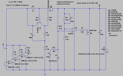
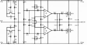
I would like to bring to your attention a simple shunt regulator which, at least in simulation, shows some promising results. The topology is not novel, I've inspired myself from the Jung regulator, the salas regulator, and a few others. Just the other day I found that Erno Borbely has designed a similar regulator.
I also have another version with the opamp replaced by bjts, which is, of course, not as good on paper.
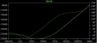
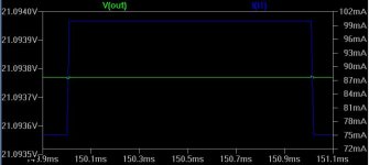
This opamp version shows some of the best psrr results of a number of regulators, including the Jung super regulator. It also shows a very good transient response to sudden changes in the load. Showed in the following posts you will see some of the simulated results. I have also built this regulator, and it looks good on the oscilloscope, but I don't have any specialized testing equipment to do more tests.
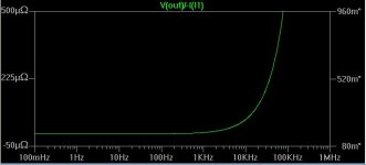
Resistor R13 should actually be 5K variable, that's what I used. That needs to be set to find the spot where oscillation does not occur. The output impedance is in the microohms until 100kHz.
All capacitors in the simulation were set to an ESR of .5 ohms and an ESL of 10nH.
Most people here will care about the sound and nothing but the sound. This is something I cannot comment on, everyone has their own idea about what sounds good.
Any comments, suggestions, are greatly appreciated.
I also have another version with the opamp replaced by bjts, which is, of course, not as good on paper.
This opamp version shows some of the best psrr results of a number of regulators, including the Jung super regulator. It also shows a very good transient response to sudden changes in the load. Showed in the following posts you will see some of the simulated results. I have also built this regulator, and it looks good on the oscilloscope, but I don't have any specialized testing equipment to do more tests.
Resistor R13 should actually be 5K variable, that's what I used. That needs to be set to find the spot where oscillation does not occur. The output impedance is in the microohms until 100kHz.
All capacitors in the simulation were set to an ESR of .5 ohms and an ESL of 10nH.
Most people here will care about the sound and nothing but the sound. This is something I cannot comment on, everyone has their own idea about what sounds good.
Any comments, suggestions, are greatly appreciated.
Attachments
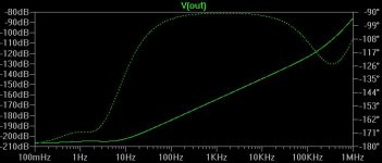
And the output impedance plot, as well as the calculated zout (calculated by the spice directive .tf v(out) v1 )
--- Transfer Function ---
Transfer_function: 2.84731e-011 transfer
v1#Input_impedance: 0.00333333 impedance
output_impedance_at_V(out): 7.63865e-008 impedance
--- Transfer Function ---
Transfer_function: 2.84731e-011 transfer
v1#Input_impedance: 0.00333333 impedance
output_impedance_at_V(out): 7.63865e-008 impedance
Attachments
Congratulations! This is the most impressive set of simulated results for any reg that I have seen so far. The fact that you have built it and it does not oscillate is a major step. I don't want you to describe the sound, but did you perceive it as different considering your previous regs? Also have you got identical line to scope's gnd? I ask because such simulated results will manifest somehow even if realized at their half potential in practice.
salas, you're too kind, but I think that it's too early for congrats.
Anyway, I thought I stop poluting your threads and create one for this regulator, since the results were surprising for me too.
Cannot say anything about the difference in sound because I haven't plugged it in the phono yet. I was looking around for a schematic to build a little "noise amp" because the oscilloscope shows as good a trace as the other one we discussed before, the opamp buffered regulator. I think better test equipment is needed to test this beast. Not only that, but it should be built with more care to layout; now it's a rat nest") only a prototype to quench my curiousity, really. Certainly looks promising.
only a prototype to quench my curiousity, really. Certainly looks promising.
Anyway, I thought I stop poluting your threads and create one for this regulator, since the results were surprising for me too.
Cannot say anything about the difference in sound because I haven't plugged it in the phono yet. I was looking around for a schematic to build a little "noise amp" because the oscilloscope shows as good a trace as the other one we discussed before, the opamp buffered regulator. I think better test equipment is needed to test this beast. Not only that, but it should be built with more care to layout; now it's a rat nest
only a prototype to quench my curiousity, really. Certainly looks promising.dodo said:R15 with c5 build a RC circuit
Difficult to argue with the above
The purpose of these parts in the Jung regulator is to make both dc and ac impedances at the opamp inputs equal. R15 doesn't seem to be helping much in this respect.
Connect R15 in series with the op-amp input and then put th e cap from th e op-amp input to ground - this is a filter.
There is no need in this type of circuit to focus too heavily on keeping the op-amp input resistances th e same since these source resistances are low enough no to cause any significant errors.
This is in any event a good sim result. I generally use 317/337 with the reference decoupled in my PSU's and then I decouple the op-amps with 22Ohms followed by 100uF right at the op-amp supply pins (I do this on each op-amp both + and - supply pins) which makes for a pretty low noise source.
I've sim'd the Jung and various shunt regulators and my view is that the shunt offers superior performance.
I don't know exact impendance of the used Zener reference
But assuming it's around -150 ohm . , if I made my math correctly 220R should be used insted of 499 to ensure eqiuval impendance on both imputs of the eror opamp
So before any final statment ...... we should ask the author about the base of his calculations
But assuming it's around -150 ohm . , if I made my math correctly 220R should be used insted of 499 to ensure eqiuval impendance on both imputs of the eror opamp
So before any final statment ...... we should ask the author about the base of his calculations
Big low ESR caps aren't optimal choice for high NFB opamp based regulators. Damping with small SMD resistor is usful. Somebody will say that better way is put in high ESR cap, but damped low ESR cap sounds otherwise than high ESR one but only experimental selection of caps and value of resistor in concrete circuit gives the best results...
but only experimental selection of caps and value of resistor in concrete circuit gives the best results...analog_sa said:
Can you publish CCS results alone?
What is the purpose of R15?
Sorry, I don't understand what you mean by "CCS results alone."
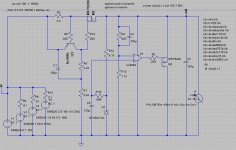
As was said, R15 and C5 were intended originally as a filter for the zener noise, in the Jung regulator, except that the in+ to the opamp was taken from between R15 and C5, as in the next picture.
Edit: psrr curve with 1000u as the output cap.
Attachments
With your latest circuit, PSSR will remain unchanged. What will improve is the output noise because you have filtered the noisy Zener.
Re the use of a big output cap. I prefer to use as big a cap as possible to keep the output impeadance low - especially at higher frequnceis where the open loop gain of the op-amp reduces. However, you have to watch that you do not introduce a pole in the loop with a low ESR cap - so this is where you have to try th e caps out to make sure the regulator remains stable.
I think some of the results we are getting in the sims are probably not acheivable (one sim showed better than -200dB!), but you should be able to get a a good, improved result.
ikoflexer said:salas, you're too kind, but I think that it's too early for congrats.
Anyway, I thought I stop poluting your threads
To the contrary, your ideas and simulations are shared wealth and stimulation. I don't believe that any idea or tweak is pollution. Good luck with the practical employment and measurements. It owes to sound it too. I would be glad to make one and subjectively ***** it when its final, and maybe there is a PCB.
- Status
- This old topic is closed. If you want to reopen this topic, contact a moderator using the "Report Post" button.
- Home
- Amplifiers
- Solid State
- Simple opamp/mosfet shunt regulator