salas said:A little OT. A question for syn08: Is Rds(on) resistance of the shunt Mosfet totally irrelevant for performance even when it shunts most of the constant current provided by the main CCS at all time? Or it has to be on the low side?
Totally irrelevant. In a linear regulator (parallel or serial) you will never drive a MOSFET to the point that Rds(on) will matter. Rds(on) is important mostly in switching applications (for which, in fact, most of the today's power MOSFETs are designed for).
Have you put a scope on the output of the op-amp (pin 6) to check that it is not oscillating?
You have a big fat pole created by the 200 Ohm output resistor and the gate input capacitance on the mosfet shunt.
I'd b e surprised if this circuit is stable in practice - it needs a bit of tweaking.
You need to reduce th e loop gain a bit - try putting a 22 to 100pF cap between the op-amp output and its inverting input. mount th e cap very close to th e op-amp (ideally use an SMD device across pins 2 and 6 on the bottom side of the board.
If you sim this tweak, you will see the performance decrease a bit - but it will still be very good.
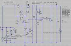
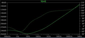
All (op)amps have a sonic signature. While being one of the best, I find LM4562 to sound a bit "hollow", lacking a bit of warmth and presence. Have you tried any other opamp?ikoflexer said:And its psrr plot. The bad news about the opamp circuit is that although the regulation seems outstanding, the sound seems to me... somehow off. I cannot trust my ears, perhaps somebody else can confirm the subjective aspect.
Bonsai said:Have you put a scope on the output of the op-amp (pin 6) to check that it is not oscillating?
You have a big fat pole created by the 200 Ohm output resistor and the gate input capacitance on the mosfet shunt.
I'd b e surprised if this circuit is stable in practice - it needs a bit of tweaking.
You need to reduce th e loop gain a bit - try putting a 22 to 100pF cap between the op-amp output and its inverting input. mount th e cap very close to th e op-amp (ideally use an SMD device across pins 2 and 6 on the bottom side of the board.
If you sim this tweak, you will see the performance decrease a bit - but it will still be very good.
Bonsai, indeed, when first plugged in it did oscillate. Recall though, that R13 is a 5kOhm variable resistor. The first thing I did is find the setting on this resistor where the opamp does not induce oscillation.
As for why it does not sound good when it looks good on the scope... it's a puzzle to me. Are Waagbo too mentioned this about his version of the opamp regulator in this article
http://www.borbelyaudio.com/pics/waagbo2863.pdf
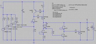
I do have a version which both looks good on paper (simulation) and give very good results in practice, even sound wise. Please see attached. It is still rough, not refined, as I came up with it only last night, and implemented it and tested on the spot.
Attachments
ikoflexer,
indeed adjusting R13 will also change the loop gain and this therefore allowed you to find a point of stability. In an amplifier circuit, you can sometimes tame loop oscillation by increasing the closed loop gain for similar reasons.
However, it is too risky to rely on this to stabilize the loop either in the case of a regularo, or an amp.
Here is what I would do as a 1st cut approach to stabilizing this loop:-
Place a 1k resistor in series with the inverting input of the op-amp from the junction of R4 and R13
Place the 22pf to 100pf cap I mentioned in the earlier post from the inverting input to the output.
You may be getting less than desireable subjective results because the regulator is going unstable intermittently. This is not a fault of the op-amp - you jus t need to compensate the loop - this takes a bit of additional effort.
http://www.borbelyaudio.com/pics/waagbo2863.pdf
I took a look at the article.
I also wonder if the author had a stability problem for similar reasons I noted above and this lead to his conclusion that the op-amp was the problem.
Your discrete regulator may be performing better because the overall loop gain is lower so you therefore run less risk of instability.
My point is, let us not point the finger at the op-amp until we are sure the loop has been compensated correctly.
So you're calling the BS-police on me? Now you tell me how it sounds! If you think it sounds like nothing, your quest is over. Not long ago people said the same thing about NE5534, OPA2132, LM6171, AD8620, OPA627 etc.Bonsai said:no b.s. please.
Ive don e extensive tests on the LM4562, and it is absolutely superb.
BTW, I've been designing with audio op-amps for 30 years so I've seen, touched used and heard most of 'em.
I agree with you, finger pointing before understanding what's going on is not good.
I will certainly implement your suggestions, the circuit is in place, and the changes are easy to make. Thank you!
This circuit has a lot of promise, perhaps with some tweaking it will deliver.
I will certainly implement your suggestions, the circuit is in place, and the changes are easy to make. Thank you!
This circuit has a lot of promise, perhaps with some tweaking it will deliver.
Sorry to pull this off topic for a second here, but to all you Toronto people know each other? I mean it's great to see so much local talent, but is this just coincidence?
On-topic - if you can bear with my newbie question - how much current would the BC560 see and how much heatsinking would this regulator need? I know there's probably 8 out of 10 on this forum that could calculate the dissipation through them, but unfortunately I'm among the uneducated.
On-topic - if you can bear with my newbie question - how much current would the BC560 see and how much heatsinking would this regulator need? I know there's probably 8 out of 10 on this forum that could calculate the dissipation through them, but unfortunately I'm among the uneducated.
Hey twitchie, I know nobody else from this forum in TO. No worries about asking any questions, as far as I'm concerned.
The bc560c dissipates about 37mW, no need for a heat sink there. The mosfets about 1.1W, I do have a heatsink for them, because I was experimenting with the circuit. It will also depend on how large the input voltage is, but with 30 to 35 volts and some heatsinks should be fine.
If you'd like to simulate this circuit let me know, I'll put all the necessary files in a place you can download. Running an ".op" simulation for instance provides all current and voltage values for all the components. Very easy and also lots of fun great video game, in a way!
The bc560c dissipates about 37mW, no need for a heat sink there. The mosfets about 1.1W, I do have a heatsink for them, because I was experimenting with the circuit. It will also depend on how large the input voltage is, but with 30 to 35 volts and some heatsinks should be fine.
If you'd like to simulate this circuit let me know, I'll put all the necessary files in a place you can download. Running an ".op" simulation for instance provides all current and voltage values for all the components. Very easy and also lots of fun
great video game, in a way!Bonsai, the modification you suggested made the regulator more unstable, sorry.
What I'm not sure is why you think that it is oscillating, when I don't see oscillation on the scope?
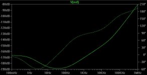
The discrete circuit has got such good results that it's less and less warranted to pursue the opamp version. It's got some other things going for it. Easier to get right, not prone to oscillations, even cheaper, I'd say. I'm still curious why the opamp version seems to sound different.
What I'm not sure is why you think that it is oscillating, when I don't see oscillation on the scope?
The discrete circuit has got such good results that it's less and less warranted to pursue the opamp version. It's got some other things going for it. Easier to get right, not prone to oscillations, even cheaper, I'd say. I'm still curious why the opamp version seems to sound different.
ikoflexer said:The discrete circuit has got such good results that it's less and less warranted to pursue the opamp version. It's got some other things going for it. Easier to get right, not prone to oscillations, even cheaper, I'd say. I'm still curious why the opamp version seems to sound different.
Things come circle in an interesting way Iko. This is essentially my first Vbe CCS shunt with 2 local IDSS connected JFETs instead of 2 resistors. And it finally seems to be all it practically takes to do the trick for you and me at least. I will use this as final for PCB with 9240s,560C,550C, 8.5mA 2SK170s in the NJFET RIAA thread, as standard for the resume posts. If you have any values to refine, please do before the weekend.
So you're calling the BS-police on me? Now you tell me how it sounds! If you think it sounds like nothing, your quest is over. Not long ago people said the same thing about NE5534, OPA2132, LM6171, AD8620, OPA627
Whats your reference?
Regrding th e op-amp/discrete debate, I just hear too many stories about how bad op-amps compared to disretes to accept without questioning.
ikoflexer, please look at the op-amp output while the circuit is running. You have an op amp with a large open loop gain, onto whicj you've bolted a mosfet increasisng th e gain even further. This system needs stabilizing.
Another option is to remove the cap you have in parallel with the feedback resistor.
- Status
- This old topic is closed. If you want to reopen this topic, contact a moderator using the "Report Post" button.
- Home
- Amplifiers
- Solid State
- Simple opamp/mosfet shunt regulator