Typical ripoff.. no way that amp will do 600W with onlyon ebay
6 of those output devices..

OS
Hi,ostripper said:
Typical ripoff.. no way that amp will do 600W with only
6 of those output devices..
OS
three pair of those Sanken 200W devices will do 350W into 4ohm 60degree phase angle inside the 100ms SOAR.
and go to 600W into 2r0 inside the DC SOAR.
It will even do 960W into 1r0 but the problem will be keeping it cool at these very high currents. Low duty cycle testing with a cold heatsink.
Re: power is a second quality
your so called stabilization method is very well known as a sonic killer .....other amps use the same thing ( very old idea ) are very stable but sound very square....
stee...Stee said:first is the stabilization method
a dual load on ground
your so called stabilization method is very well known as a sonic killer .....other amps use the same thing ( very old idea ) are very stable but sound very square....
Good to know Sakis
Catalin
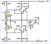
one idea
if driver and final on CFPhave the same devices
total gain is the same
for example if NPN have gain 50 (hFE) and PNP 100
complessive factor is same in the opposite rail
PNP 100 connect to NPN 50
this can raise job on feedback to compense this gap
and ensure stability with natural sound
(for less crossover distortion)
it's an idea not a thesys

Catalin
one idea
if driver and final on CFPhave the same devices
total gain is the same
for example if NPN have gain 50 (hFE) and PNP 100
complessive factor is same in the opposite rail
PNP 100 connect to NPN 50
this can raise job on feedback to compense this gap
and ensure stability with natural sound
(for less crossover distortion)
it's an idea not a thesys
Attachments
Re: Good to know Sakis
Hello stee ,
I really share your ideea about mixing cfp+ef but just teoretical now.javascript:smilie('')
"if driver and final on CFPhave the same devices
total gain is the same" what do you want to say here ?
How the gain will be the same ?
Stee said:
Catalin
one idea
if driver and final on CFPhave the same devices
total gain is the same
for example if NPN have gain 50 (hFE) and PNP 100
complessive factor is same in the opposite rail
PNP 100 connect to NPN 50
this can raise job on feedback to compense this gap
and ensure stability with natural sound
(for less crossover distortion)
it's an idea not a thesys
Hello stee ,
I really share your ideea about mixing cfp+ef but just teoretical now.javascript:smilie('
') "if driver and final on CFPhave the same devices
total gain is the same" what do you want to say here ?
How the gain will be the same ?
Copule's Solution
I want to say that changing the position of the factors
the result does not change
hence
the complessive gain between the upper rail
are equivalent to the lower rail
if you are using components of the same rank
even though they are different (PNP and NPN hFE)
I want to say that changing the position of the factors
the result does not change
hence
the complessive gain between the upper rail
are equivalent to the lower rail
if you are using components of the same rank
even though they are different (PNP and NPN hFE)
Attachments
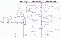
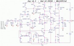
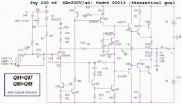
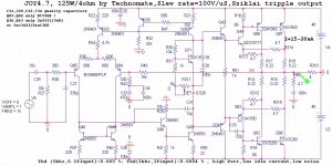
I have finished my amp and this is final schematic which is working .
I will stop my search for audio amplifiers development here .
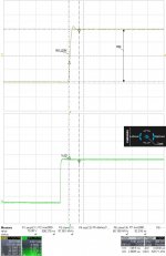
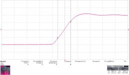
This version is 4.7 and it has :
Slew rate = 100V/uS measured with oscilloscope at 1khz,10 and 20khz .
low thd at high frequency 5,10,20khz below 0.00x with 0.1 output voltage .
low idle current (benefit from sziklai output) and low noise .
enough phase reserve and gain reserve .
open loop gain =110dB .
high linearity and high dynamics .
The main challenge was to design it by using small capacitors for VAS so we have 12pF right there
best sound so far .
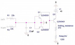
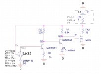
It has 2 small circuits ,one is a simple fan controller with lm35 sensor mounted on the heatsink and second is dc-protection for speakers .
I will stop my search for audio amplifiers development here .
This version is 4.7 and it has :
Slew rate = 100V/uS measured with oscilloscope at 1khz,10 and 20khz .
low thd at high frequency 5,10,20khz below 0.00x with 0.1 output voltage .
low idle current (benefit from sziklai output) and low noise .
enough phase reserve and gain reserve .
open loop gain =110dB .
high linearity and high dynamics .
The main challenge was to design it by using small capacitors for VAS so we have 12pF right there
best sound so far .
It has 2 small circuits ,one is a simple fan controller with lm35 sensor mounted on the heatsink and second is dc-protection for speakers .
Attachments
Last edited:
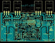

Hi Alex....... and PCB for this nice sounding amplifier right here
Alex .
I am interested on this amp (I like Szikai) but it seems to me that you are putting the VBE transistor on the same H/S of the OP, from your layout.
The thermal tracking should be better if it would be thermally coupled only to the drivers. Or does this not hold true any more since this is a "triple" ?
I am interested about the thermal stability of the Sziklai output stage.
I wonder about the 0.22 ohm resistors.
On some designs I see them at the emittors of the Output transistors.
On some designs I see them, like in this amplifier, at the "emittors" of the "Compound transitor".
From simulations on a similar design, I found the second way is far more, temperature stable than the first way. There is much less varation of the quiescent current from ouput transistor temperature variations.
Have you experimented about these two ways to put those resistors.
What difference have you seen about thermal stability and circuit stability ( oscillations/ ringing ).
Well of course that is have to have the resistor on the emitter.In this way we have negative reaction on that Vbe .But we have more negative reaction by putting on the "compound" .
The question is "how much is worth to increase the thermal stability" ?
Here the thermal reaction is doing quite well .
If we set for example a 20 mA for 35 degrees Celsius on the heatsink and then heating the powerstage to raise heatsink temp at 50 degrees the current is going to 17mA which is pretty good .This is measured at my amp.
If you want to understand perfectly you can have a look at Self and Pass books.
The circuit is very stable.On some layouts that 82 pf is required on others not .That's why I inserted also in schematic.
But only with components from schematic.If you don't have 2sc5171 and want to replace with something else you must to look for that 15pf Cob .
I know other guys which didn't have 2sc5171 and try with mje15030 .But Cob differs a lot .For that they need to compensate the local feedback by putting a 100pF between colector and base for each prefinal .But only if we don't have 2sc5171 or equivalent .
Last edited:
You will most probably need to match the ""slaves" of the CFP, because there is no emitter degeneration applied to the SA/SC output transistors.
It would be wise to apply some degeneration resistors if you are use multiple pairs.
As I said there is no reason to fear this topology.the amp is going very well even at high temperatures for about 4-5 years in this topology.
The transistor are not well matched but this is not an issue.Please read again and if you can and have time read those books also .
Last edited:
- Status
- This old topic is closed. If you want to reopen this topic, contact a moderator using the "Report Post" button.
- Home
- Amplifiers
- Solid State
- a wonderfull sziklai